
Aug 21, 2026
How to Control 0.005 mm Coaxiality in Black-Anodized Optical Lens Barrels
Learn how to control thin-wall distortion, anodizing buildup, bore dimensions, and 0.005 mm coaxiality in CNC-machined optical lens barrels through DFM, CMM inspection, and prototype validation.
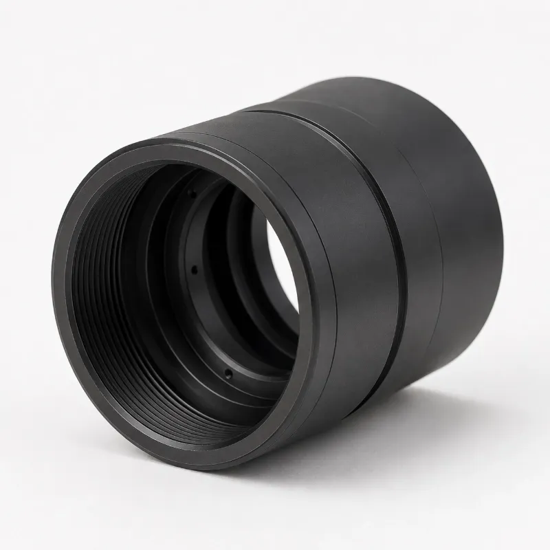
A typical optical barrel drawing may specify 6061-T6 aluminum, black anodizing, an internal mating surface of Ra ≤ 0.8 μm, coaxiality of 0.005 mm, a 1.2 mm wall thickness, an overall length of 85 mm, and a prototype deadline within 15 days.
The difficulty becomes clear when you contact suppliers.
One machine shop can hold the machining tolerance but outsources anodizing and will not take responsibility for the final dimensions. Another provides a good black finish but can only hold 0.01 or 0.02 mm coaxiality. A third offers a low price, but plans to verify 0.005 mm coaxiality with only a dial indicator.
For an optical assembly, none of these answers is enough.
An optical lens barrel locates the lens stack relative to the mount, sensor bracket, and other optical components. Clamping distortion, datum-transfer error, or anodizing variation can cause difficult lens installation, optical-axis misalignment, reduced image quality, or complete assembly rejection.
The real requirement is usually not to achieve 0.005 mm before finishing. It is to meet the drawing in the final delivery condition after black anodizing. That requires a controlled chain from DFM and fixturing to machining, finishing, and inspection.
Three Main Risks Behind This Part
1. Thin-Wall Distortion During Clamping
With a wall thickness of only 1.2 mm and a length of 85 mm, the barrel can deform under conventional chuck pressure. It may appear round while clamped, then spring back after release and change the bore roundness, outside diameter, and relationship between the critical axes.
A reliable supplier should begin with a DFM review covering:
- Wall-thickness distribution and local weak areas
- Datum relationships between the bore, outside diameter, and end faces
- Features that should share one setup or datum system
- Stress release between roughing and finishing
- Anodizing allowance for bores, threads, and mating surfaces
- The final inspection method
Depending on the geometry, TengRui Precision may evaluate low-stress soft jaws, controlled clamping force, internal support, custom fixtures, or staged machining. The objective is to reduce local pressure and keep the machining and inspection datums consistent.
Even with a suitable fixture, 0.005 mm coaxiality should be validated through first-article and small-batch trials rather than promised from theory alone.
2. Black Anodizing Changes Functional Dimensions
Black anodizing is not only a color treatment. It creates a real oxide layer on the aluminum surface. Bore diameters, threads, shoulders, and mating features may all change after treatment, and the coating may not be perfectly uniform across internal and external surfaces.
For a lens press-fit or precision locating bore, an uncontrolled allowance can cause:
- A bore that is too small for assembly
- Excessive interference and stress in the lens
- Uneven tight and loose areas
- Tight or incomplete thread engagement
- Dimensions that pass before anodizing but fail afterward
- Rework that removes the black optical surface
The first DFM question should be: Does the drawing define the dimension before anodizing or in the final anodized condition?
If the optical bore must retain a continuous black surface, the pre-anodized dimension, coating target, racking method, and process allowance must be planned together. If a precision locating surface may remain uncoated, selective masking can be considered.
Post-anodizing honing, grinding, or cutting should only be used when the drawing permits it and the customer has approved the effect on corrosion resistance, appearance, and stray-light performance. Restoring a bore dimension by cutting through the anodized layer may solve a dimensional problem while creating an optical one.
3. Inspection Must Match the Drawing Datums
A dial indicator is useful for in-process runout checks, but runout is not automatically the same as drawing-defined coaxiality. Results can be affected by the rotating setup, part roundness, contact position, and holding datum.
For a 0.005 mm geometric requirement, the inspection plan should identify:
- The datum feature establishing the reference axis
- The exact geometric characteristic being controlled
- The inspection equipment and measurement strategy
- How inspection fixturing will avoid thin-wall distortion
- How results will be traced to the drawing revision and batch
TengRui Precision uses ZEISS or Hexagon CMM equipment together with surface-roughness inspection in a 22 ± 1°C controlled environment. Depending on the project, the quality package can include FAI, SPC, CPK, a control plan, and PPAP-related documents.
The equipment name alone is not the guarantee. The measurement program must reproduce the drawing datums and provide repeatable results.
Why 0.005 mm Is a Conditional Capability
At 0.005 mm, coaxiality should be treated as a project-specific requirement. The result may be affected by spindle condition, tool wear, fixture design, springback, secondary setups, aluminum residual stress, temperature, CMM strategy, and anodizing variation.
Instead of asking only, “Can you hold 0.005 mm?”, ask which datum establishes the axis, which features share one datum system, how pre- and post-anodizing targets are defined, and how the finished first article will be inspected.
TengRui Precision reviews ±0.005 mm dimensional tolerances and 0.005 mm-level geometric controls against the actual drawing, geometry, material, and finishing condition before commitment. This identifies risk before production instead of leaving it for incoming inspection or assembly.
A Lower-Risk 15-Day Prototype Plan
For an overseas optical-equipment company developing an industrial camera or machine-vision module, a safer route is:
Step 1: Confirm the Drawing and Assembly Function
Review the A/B/C datums, lens-fit condition, coating target, and surfaces that must remain black. If both STEP and PDF files are supplied, confirm that their revisions and critical dimensions agree.
Step 2: Complete the DFM Review
Evaluate thin-wall regions, clamping positions, tool access, roughing and finishing sequence, anodizing allowance, masking, and inspection. Any design suggestion should be implemented only after written customer approval.
Step 3: Validate One or Two First Articles
Record bore size, roundness, coaxiality, and roughness before anodizing. Inspect the parts again after finishing in the final delivery condition. The customer should receive a before-and-after comparison, not only pre-anodizing data.
Step 4: Check Small-Batch Stability
After first-article approval, use a small run—often 5 to 10 parts—to review variation. Before volume production, evaluate critical characteristics with an appropriate data set.
CPK ≥ 1.33 is a common target when the process is stable and the measurement system is suitable.
One successful prototype does not prove that the process is ready for production.
Four Items to Lock Down Before Approval
- Final-condition FAI: The report should represent the cleaned, anodized, ready-to-ship part.
- Before-and-after data: Record critical bores and threads before and after anodizing.
- Measurement method: Confirm how the CMM establishes the drawing datums.
- Production control: Define SPC, CPK, sampling, and deviation handling for critical features.
These controls reduce international rework shipments, time-zone delays, and assembly uncertainty.
Why Include TengRui Precision in Your Supplier Evaluation?
For a precision lens-barrel project, the useful question is not how long a supplier’s company profile is. It is whether the supplier can identify the drawing risks, propose a practical process, and verify the finished component with data.
TengRui Precision provides OEM precision manufacturing services to customers worldwide, with 3-axis and 5-axis CNC machining, precision inspection, and coordinated surface-finishing support under an ISO 9001:2015 quality management system.
Support for overseas projects includes:
- MOQ 1 for prototype and low-volume validation
- DFM review before committing to ±0.005 mm-level requirements
- FAI, SPC, CPK, control plans, and project-specific quality documents
- Chinese-English NDA support and controlled drawing management
- Prototype fees that can be credited toward a subsequent production order
- International delivery through carriers such as DHL, with insurance available when required
The goal is to verify dimensional, finishing, and assembly risks with a small initial order before increasing production volume.
FAQ
How can 0.005 mm coaxiality be maintained after black anodizing?
The machining datums, thin-wall fixture, coating allowance, racking or masking plan, and final inspection must be controlled together.
The finished part should be measured against the drawing datums after anodizing. Any operation that could remove the black layer requires customer approval.
How much will anodizing change the bore diameter?
There is no single value for every barrel. The change depends on anodizing type, coating thickness, bore geometry, racking, and process stability.
Measure the first article before and after anodizing, then use the actual data to refine the machining allowance.
Can a dial indicator verify 0.005 mm coaxiality?
A dial indicator is useful for process runout checks, but it does not automatically reproduce drawing-defined coaxiality.
A datum-based CMM inspection is normally more suitable, with the method and result documented in the report.
How can an overseas buyer reduce first-order risk?
Start with MOQ 1 or a small prototype batch. Verify the critical dimensions, anodized appearance, and assembly fit before scaling production.
Request FAI data, control drawing revisions in writing, sign an NDA, and use suitable export packaging and shipping insurance where needed.
Request a DFM Review
Have a black-anodized optical barrel or another precision optical component under development?
Send TengRui Precision your 2D drawing and STEP file. We can review the critical datums, thin-wall risks, anodizing allowance, and inspection plan before you commit to prototype production.