
Aug 21, 2026
CNC Machining POM Robot Housings: How to Improve Dimensional Stability
Learn how to improve dimensional stability in CNC-machined POM robot housings through DFM, low-stress fixturing, heat control, staged machining, and reliable inspection.
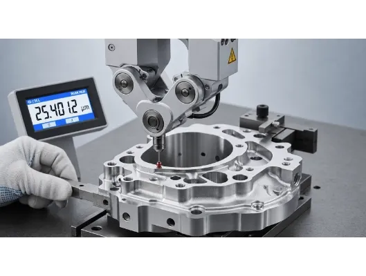
POM robot housings are lightweight, wear-resistant, and easy to machine. However, maintaining tight tolerances after machining is more difficult than it first appears.
A bearing bore may pass inspection immediately after machining but drift after the part is unclamped or left overnight. A sealing surface may be flat during in-process inspection but deform before assembly. Hole positions may also change when the housing moves between machining, inspection, shipping, and the customer’s production environment.
These problems are not always caused by inadequate CNC accuracy. They are often related to residual stress, thermal expansion, uneven material removal, clamping pressure, and inconsistent inspection conditions.
For overseas robotics companies, the real question is not simply whether a supplier can machine POM. It is whether the supplier can control the variables that affect the part after it leaves the machine.
Why POM Robot Housings Lose Dimensional Accuracy
Critical features on a robot housing commonly include:
- Bearing bores
- Motor mounting interfaces
- Sealing surfaces
- Locating shoulders
- Dowel holes
- Metal insert areas
- Mating surfaces between the housing and frame
A tolerance of ±0.02 mm may appear achievable based on machine positioning accuracy. However, POM expands and contracts significantly more than aluminum or steel.
Depending on the grade, unfilled POM typically has a coefficient of linear thermal expansion of approximately 95–110 × 10⁻⁶/K. On a 100 mm feature, a temperature change of only 5°C may theoretically produce a dimensional change approaching 0.05 mm.
This means a part measured while still warm may produce a different result after reaching the inspection-room temperature. The same part may change again when delivered to a customer operating in a different environment.
Residual stress creates another risk. Extruded sheets, rods, molded blanks, POM-C, POM-H, and filled POM grades do not behave in exactly the same way. Removing a large amount of material from one side of a blank can disturb the internal stress balance and cause the housing to bend, twist, or shrink.
Before machining begins, the supplier should therefore confirm:
- The exact POM grade
- Whether the material is unfilled or modified
- The blank manufacturing method
- The material batch and supporting documentation
- The functional temperature range
- The inspection reference temperature
- The dimensions that directly affect assembly
Without this information, tightening the CNC machine tolerance alone will not provide reliable dimensional stability.
DFM Review: The First Control Point
A proper design for manufacturability review should identify risks before the customer pays for tooling, fixtures, or a full production batch.
For a POM robot housing, the DFM review should focus on four areas.
Critical Assembly Dimensions
Bearing bores, sealing surfaces, locating shoulders, and interface holes should be separated from non-critical dimensions. This allows the machining and inspection plan to concentrate on features that can stop assembly or affect robot performance.
The drawing should also provide clear datums. If the machining datum, design datum, and inspection datum are different, every datum transfer introduces additional variation.
Wall Thickness and Material Removal
Thin walls and asymmetric pockets are particularly sensitive to stress release. If one side of a housing is heavily machined while the other side remains thick, the part may deform after unclamping.
Balanced wall thickness and more symmetrical material removal can significantly reduce this risk. Where the design cannot be changed, the process should use staged machining and intermediate measurement.
Tool Accessibility
Deep cavities, narrow slots, internal corners, and closely spaced ribs may require long, small-diameter tools. Although the geometry can be modeled in CAD, it may not be practical to machine with a stable standard tool.
For example, if two ribs are only 6 mm apart, a long-reach Ø4 mm cutter may be required. Tool deflection, surface finish, machining time, and breakage risk should be reviewed before quotation.
Tolerance Stack-Up
A POM housing often interfaces with metal brackets, bearings, O-rings, motors, or transmission components. Every individual part may meet its drawing tolerance while the final assembly still becomes too tight or too loose.
A 3D tolerance and interference review helps identify this risk before prototype assembly. In some cases, adjusting a non-functional tolerance or clarifying the inspection condition can reduce cost without affecting performance.
At TengRui Precision, the purpose of DFM is not to redesign a customer’s product without approval. It is to highlight machining and assembly risks early so the customer can make an informed decision before production.
Low-Stress Fixturing for Thin-Wall Housings
Clamping is one of the most common causes of POM housing distortion.
POM is less rigid than metal. Concentrated pressure from hard jaws or conventional clamps can deform the part before cutting starts. The housing may appear correct while clamped but spring back after removal.
Depending on the geometry, suitable workholding methods may include:
- Profile-matched soft jaws
- Vacuum fixtures
- Internal expanding supports
- Large-area support surfaces
- Low-pressure mechanical clamping
- Dedicated fixtures for secondary operations
Vacuum workholding can distribute force more evenly, but it is not suitable for every design. Through-holes, rough surfaces, insufficient sealing areas, or very thin sections may lead to vacuum leakage or suction-induced deformation.
A more reliable method is to validate the fixture using three measurements:
- Measure the critical feature while the part is clamped.
- Measure it again immediately after unclamping.
- Recheck it after the part reaches a stable temperature.
If the dimensions change significantly between these stages, the supplier should adjust the fixture, support location, clamping force, or machining sequence. Applying additional tool compensation without addressing the clamping problem will only hide the root cause.
Fixture contact surfaces must also be clean and free from burrs. Even a small chip trapped under a locating surface can affect flatness or leave a permanent mark on the relatively soft POM surface.
Separate Roughing and Finishing
Machining a POM housing to its final dimensions in one operation increases the risk of post-machining movement.
Roughing removes the largest amount of material and generates the greatest change in the part’s internal stress balance. A controlled process therefore separates roughing, semi-finishing, and final finishing.
A typical starting strategy may include:
- Rough machining with approximately 0.5–1 mm stock per side
- A controlled relaxation period or intermediate stress-relief process
- Re-establishing the datum
- Semi-finishing with a small, even allowance
- Measuring critical features
- Final machining after the dimensions become stable
These values are not universal. The correct allowance depends on the blank size, POM grade, wall thickness, geometry, and tolerance.
The machining sequence should also maintain support for as long as possible. Finishing the external profile too early may leave insufficient support when the internal cavity is machined. Removing the entire cavity in one step may cause the outer walls to move.
Staged and balanced material removal is generally more reliable than machining one side completely before starting the other.
A fixed 24-hour waiting period is not mandatory for every POM component. The required stabilization time should be determined through measurement. The important point is to compare dimensions before and after the selected interval and confirm that the part is no longer showing an unacceptable trend.
Control Cutting Heat Instead of Chasing Machine Accuracy
POM has relatively low thermal conductivity. If heat accumulates near the cutting edge, the material can expand, soften, produce burrs, or deflect under cutting force.
A dimension machined while the material is warm may become undersized after cooling.
POM cutting parameters should therefore not be copied directly from an aluminum or steel program. Spindle speed, feed per tooth, depth of cut, tool diameter, and cooling method must be validated together.
The process should use:
- Sharp cutting edges
- Polished flutes with adequate chip space
- Positive cutting geometry where appropriate
- Controlled chip load
- Effective chip evacuation
- Clean compressed air or an approved cooling method
- Tool-life monitoring
Sharp, polished carbide tools are suitable for many unfilled POM applications. PCD tools may be considered for long production runs, abrasive filled grades, or demanding surface-finish requirements, but they are not mandatory for every POM part.
Very high spindle speed combined with insufficient feed can cause rubbing instead of cutting. Excessive feed or a worn tool can increase cutting force and push a thin wall away from the cutter. The correct process window is the combination that controls both heat and deflection.
Deep pockets and narrow slots require particular attention to chip evacuation. Recutting trapped chips may scratch finished surfaces and create localized heat.
Before batch production, TengRui Precision validates the machining window using several consecutive parts rather than relying only on one first article. Bore size, position, flatness, and dimensional trends can then be compared before the program and tool offsets are released for production.
Temperature and Moisture: Control the Right Variable
POM absorbs much less moisture than nylon, so short-term humidity exposure is not normally the primary cause of dimensional drift. Temperature, residual stress, clamping, and structural stiffness usually deserve greater attention.
However, moisture should not be ignored when a component will operate in a hot, wet, or fluid-contact environment. The exact effect depends on the selected POM grade and should be evaluated using the material supplier’s data.
Drying and heat treatment should not be applied as fixed rules to every POM component. Parameters such as “80°C for two hours” or “anneal every finished part” may be unsuitable for a particular grade or geometry.
If annealing is required, the temperature, holding time, and cooling rate should be based on:
- The material supplier’s recommendations
- The blank thickness
- The manufacturing method
- The amount of material removed
- The required dimensional tolerance
Heat treatment can itself cause shrinkage or warping. The machining plan should therefore reserve sufficient finishing stock and include dimensional inspection after cooling.
Packaging should protect parts from scratches, contamination, rapid environmental changes, and mechanical pressure during international shipping. Individual bags, moisture-resistant packaging, or vacuum packaging can be selected according to the customer’s storage conditions, but vacuum packaging is not automatically required for every POM housing.
Inspection Data That Supports Batch Stability
One acceptable prototype does not prove that a process is ready for production.
For batch manufacturing, critical dimensions should be monitored through a defined inspection plan. Depending on the risk level, this may include:
- Full first article inspection
- In-process inspection at defined intervals
- Critical-dimension checks on each part
- Final inspection
- SPC monitoring
- CPK analysis when sufficient data are available
TengRui Precision uses ZEISS and Hexagon CMM systems, Mitutoyo surface roughness equipment, and calibrated precision measuring instruments for process and final inspection.
Machine probes may be used to verify datums and selected features, but machine measurement should not automatically replace independent final inspection. Machine temperature, probe calibration, measurement direction, and tool condition can all influence the result.
CPK ≥ 1.33 is a common target for a mature production process. However, a meaningful CPK calculation requires a stable process, a capable measurement system, and enough data. Three or five prototype parts are not sufficient to demonstrate long-term process capability.
During prototyping, the better indicators are:
- Dimensional range
- Mean position within the tolerance
- Change after unclamping
- Change after thermal stabilization
- Repeatability between consecutive parts
Once production data are available, SPC can reveal dimensional trends before parts exceed the specification. For example, a bearing bore may gradually move toward its upper limit because of tool wear. Correcting the process at this stage is less costly than sorting or remanufacturing an entire batch.
A Lower-Risk Validation Route
For a new POM robot housing, moving directly from drawing approval to mass production creates unnecessary risk.
A staged validation route is more reliable:
- Machine one or two prototypes to verify tool access, datum strategy, surface quality, and basic dimensions.
- Produce five to ten parts to evaluate unclamping movement, thermal stabilization, and actual assembly.
- Run a representative pilot batch to collect process data and confirm repeatability.
- Lock the material grade, fixture, program, inspection method, and packaging specification before volume production.
This approach adds an initial validation stage but reduces the risk of discovering tight bearing fits, warped sealing surfaces, or shifted mounting holes after a full batch has already been completed.
The customer is not only protecting the unit cost of the machined parts. More importantly, this process helps avoid assembly delays, engineering changes, line stoppages, and repeated international shipments.
Frequently Asked Questions
Can a CNC-machined POM robot housing consistently hold ±0.02 mm?
It may be achievable on selected features, but capability must be evaluated against feature size, wall thickness, geometry, POM grade, temperature, and inspection method. A small bearing bore and a large hole-to-hole distance may carry the same drawing tolerance but present very different machining risks.
Does every POM part require 24 hours of stress relaxation?
No. Twenty-four hours may be used as an initial validation condition, but it is not a universal requirement. The necessary stabilization time should be determined by comparing actual measurements over time.
Must POM be machined with diamond tools?
No. Sharp, polished carbide tools are suitable for many POM components. PCD tools may offer advantages for abrasive filled grades, demanding finishes, or longer production runs.
Is annealing always required?
No. Annealing should be based on the material grade, blank condition, geometry, and dimensional requirements. Unnecessary or incorrectly controlled heat treatment can create additional dimensional changes.
How should batch stability be verified?
Critical dimensions should be monitored using a defined inspection plan. Prototype parts should be checked for dimensional range and post-machining movement. Once sufficient production data are available, SPC and CPK analysis can be used to evaluate process stability.
Conclusion
Dimensional stability in CNC-machined POM robot housings cannot be achieved by machine accuracy alone.
Reliable results depend on controlling the complete process: material selection, DFM review, balanced stock removal, low-stress fixturing, cutting heat, stabilization time, inspection temperature, and batch data.
TengRui Precision supports overseas robotics companies from drawing review and prototype machining through pilot production and volume manufacturing. Starting with a small validation batch allows critical tolerances and assembly risks to be confirmed before production is expanded—helping customers reduce rework, delays, and the overall cost of trial and error.