
Sep 15, 2026
Drone Gyroscope Housing CNC Machining: Controlling Thin-Wall Deformation and Batch Consistency
Learn how DFM, stress relief, controlled fixturing, 5-axis CNC machining and ZEISS CMM inspection improve drone gyroscope housing batch consistency.
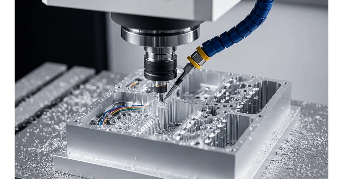
In September 2026, an overseas R&D team developing gyroscope housings and inertial navigation components for unmanned aerial vehicles encountered a problem during its third assembly validation run.
The gyroscope housing was a thin-walled, curved aluminum component with an array of mounting holes on the outer wall and a precision sealing surface on one end.
The first prototypes supplied by two previous CNC machining companies appeared acceptable. Their dimensional inspection reports did not show any obvious problems.
However, during the second and third production batches, the mounting-hole positions began to drift. Coaxiality on some related features exceeded 0.06 mm, while inconsistent contact appeared along the sealing surface.
The assembly team had to stop production and inspect the housings individually.
The customer’s structural engineer described the problem clearly:
The issue is not whether a supplier can make one acceptable part. The issue is whether the next batch will still be the same.
This situation is not unusual in drone parts CNC machining.
Finding a supplier that can machine an aluminum housing is relatively easy. Finding one that understands thin-wall deformation and can maintain the position, flatness, coaxiality, and assembly performance of critical features from one batch to another is much more difficult.
For procurement engineers, mechanical designers, and supply chain managers, the main risks usually fall into three categories:
- The prototype passes inspection, but dimensions begin to drift during small-batch production.
- The quotation does not clearly explain tooling, inspection, surface finishing, or other potential costs.
- The stated lead time covers only machining and does not account for fixture preparation, stress relief, surface treatment, inspection, or international shipping.
When TengRui Precision Machinery reviewed this project, the first step was not to start cutting material immediately.
The engineering team first carried out a DFM review focused on the thin-wall areas, locating datums, material-removal ratio, sealing surface, mounting-hole relationships, and inspection conditions.
The initial conclusion was that the problem was not primarily machine accuracy. The greater risks were the fixturing method, the residual-stress release sequence, and the lack of a clearly defined measurement condition for critical dimensions.
These factors may remain hidden during one-piece prototyping but become visible after 20, 50, or more parts are machined continuously.
Why Can a Prototype Pass Inspection While Later Batches Fail?
The customer’s symptoms were specific:
- The first article passed CMM inspection.
- Mounting-hole position began to exceed tolerance during the third batch.
- Sealing-surface flatness shifted from approximately 0.02 mm to approximately 0.05 mm.
- Gyroscope bias repeatability became less stable after assembly.
- The assembly team had to sort parts individually.
The resulting cost was not limited to a few rejected housings.
It included sorting, reinspection, rework, rescheduling, engineering review, delayed assembly, and repeated communication between the customer and supplier.
For a UAV or inertial navigation project still in the validation stage, a delay of several weeks can affect flight testing, customer demonstrations, qualification schedules, and product launch plans.
The causes of this type of failure can usually be examined in three areas:
- Fixturing and clamping deformation
- Residual stress and machining sequence
- Measurement conditions and inspection methods
1. Fixturing Deformation: Accurate While Clamped, Out of Tolerance After Release
Thin-walled curved housings have limited structural rigidity.
If a conventional three-jaw chuck or vise applies excessive localized force, the housing may deform elastically during machining. Because cutting and in-process measurements are performed while the workpiece is clamped, the dimensions may appear correct at that moment.
Once the fixture is released, the wall springs back.
This movement can affect:
- Hole position
- Circularity
- Coaxiality
- Sealing-surface flatness
- The relationship between mounting features
- Final assembly fit
If an array of mounting holes is located near a high-clamping-force area, its positional accuracy may also vary with small changes in clamping pressure from one setup to another.
This does not necessarily indicate insufficient machine accuracy. It often means that the fixture was not designed around the flexibility of the part.
Depending on the geometry, TengRui may evaluate several approaches:
- Using a rigid setup for rough material removal
- Adding temporary machining tabs or clamping bosses to the blank
- Supporting thin-wall areas with a form-fitting fixture during finishing
- Using custom soft jaws to increase the contact area
- Using vacuum holding when the geometry and cutting forces allow it
- Standardizing clamping force and setup parameters
- Machining related holes and sealing features within the same datum system
- Minimizing repeated setups on critical interfaces
Vacuum holding is not automatically the best answer for every thin-wall part.
The available sealing area, vacuum stability, cutting direction, tool load, wall thickness, and fixture contact pattern must all be reviewed. A suitable fixture has to be developed around the actual housing rather than selected only because the component is thin-walled.
The purpose is not simply to hold the workpiece firmly. It is to support the part without changing the geometry that the machining process is intended to create.
2. Residual Stress: The Part May Continue to Move After Machining
A thin-wall aluminum housing often requires a large percentage of the original material to be removed.
As material is removed, the residual stress inside the blank redistributes. If roughing and finishing are completed continuously without allowing the part to stabilize, the housing may continue to move after it leaves the machine—or even after surface treatment.
This effect can be difficult to detect during one-piece prototyping.
During continuous production, however, differences in material condition, machining temperature, setup duration, clamping force, and stabilization time can cause part-to-part variation.
Hole position, flatness, wall profile, and coaxiality may then begin to drift.
For components with a high material-removal ratio, a typical process route may be:
Rough machining → Stabilization or stress relief → Semi-finishing → Deformation check → Final machining
The exact process depends on:
- Aluminum alloy and temper
- Whether the raw material is plate, extrusion, forging, or casting
- Wall thickness and pocket depth
- Percentage of material removed
- Flatness and positional tolerances
- Surface-treatment requirements
- Order quantity
- Delivery schedule
For some thin-wall housings, an appropriate finishing allowance may be retained after rough machining. For example, approximately 0.5 mm per side may be suitable in certain cases, but the actual allowance must be determined from the component size, geometry, deformation trend, and final tolerance.
Adding a stabilization step can increase the manufacturing cycle time of an individual part. However, it may reduce the much greater cost of batch rejection, sorting, rework, and delayed assembly.
From the customer’s perspective, the important question is not whether one machining operation can be completed faster. It is whether the entire batch can enter assembly according to plan.
3. Measurement Conditions: Free-State Inspection Is Not Always Assembly-State Inspection
Another frequently overlooked issue is the condition in which a thin-wall component is measured.
A drawing may define dimensions that are functionally important in the final assembled state, while the machining supplier inspects the component in an unsupported free state.
The results may not be identical.
For example:
- Mounting-hole position must be measured from a clearly established datum system.
- Sealing-surface flatness may need to be checked under simulated assembly restraint.
- Circularity and coaxiality of a thin cylindrical wall can be influenced by inspection fixturing.
- Hole sizes and mating dimensions may change after anodizing.
- The tightening sequence of assembly screws may alter the final contact pattern.
If the customer and supplier do not agree on the measurement condition during first article approval, both parties can obtain different results from the same component.
The supplier’s report may show that the part is acceptable, while the customer may still experience assembly failure.
During DFM and inspection planning, TengRui therefore recommends confirming:
- Whether each critical feature is measured in a free, clamped, or simulated assembly state
- Which datums are used to establish the coordinate system
- Which dimensions require ZEISS CMM inspection
- Whether sealing surfaces require feeler-gauge or simulated assembly verification
- Which dimensions are controlled before and after surface treatment
- Whether the inspection report must state the measurement condition
- Whether a dedicated checking fixture is required
For components with significant assembly restraint, both free-state and simulated assembly-state data may be retained.
This helps distinguish actual machining deviation from dimensional changes caused by assembly forces.
The Main Variables That Affect Batch Consistency
Control Area | Common Problem | Recommended Control Method | Customer Benefit |
|---|---|---|---|
Fixturing | Thin walls deform under localized clamping force | Form-fitting support, custom soft jaws, vacuum holding, or machining tabs | Reduces springback and setup variation |
Residual stress | Flatness and hole position change after roughing | Separate roughing, stabilization, semi-finishing, and finishing | Reduces dimensional drift after machining |
Datum control | Multiple setups create accumulated positioning error | Optimize the 5-axis machining route and reduce unnecessary repositioning | Improves relationships between holes, bores, and sealing surfaces |
Measurement condition | Part passes in a free state but fails during assembly | Define free-state or restrained-state measurement during DFM | Reduces inspection disputes |
First article inspection | A prototype passes without complete dimensional evidence | Provide an FAI full-dimensional report | Identifies drawing and process risks before small-batch production |
Batch inspection | Later lots lack consistency data | Establish sampling frequency and SPC/CPK records for critical features | Shows whether the process remains stable |
Engineering changes | A revised design is produced using the old process | Reassess fixtures, toolpaths, allowances, and datums | Prevents unvalidated changes from entering production |
Machine accuracy is important, but machine accuracy alone cannot guarantee repeatable production.
The result also depends on whether:
- The process route is appropriate
- The fixture can reproduce the same locating condition
- Clamping force is controlled
- Material condition is stable
- Inspection methods are consistent
- Critical dimensions are supported by batch data
How 5-Axis CNC Machining Helps Reduce Datum-Transfer Error
Drone gyroscope housings and inertial navigation components often combine multiple machined faces, internal cavities, curved surfaces, mounting-hole arrays, and precision assembly interfaces.
When these features are produced through multiple three-axis setups, each new setup introduces another opportunity for locating error.
An individual setup error may be small. However, when hole position, coaxiality, sealing surfaces, and center bores are related through geometric tolerances, several small errors can accumulate into an assembly problem.
TengRui uses Mazak 5-axis CNC machining equipment for complex multi-face components when the geometry and process requirements justify it.
The purpose is to reduce unnecessary setups and machine related features within a consistent coordinate system.
Potential benefits include:
- Fewer datum transfers
- Improved positional relationships between hole arrays and center bores
- Better consistency between sealing surfaces and mounting features
- Reduced work-in-process handling
- Lower risk of impact damage between operations
- More efficient machining of complex multi-face geometries
However, 5-axis CNC machining does not mean that every feature should always be completed in one setup.
Thin-wall components that require stress stabilization may still need separate roughing and finishing operations. The correct objective is to eliminate unnecessary setups without ignoring material behavior.
A well-planned two-stage process can be more stable than forcing the entire part to be machined in one continuous operation.
How Inspection Data Can Show Whether a Process Is Stable
A passing first article proves that one part met the specified requirements under a particular machining and measurement condition.
It does not prove that future batches will remain stable.
Before moving from a prototype into small-batch production, the customer and supplier should identify three to five dimensions that directly affect function or assembly.
For a drone gyroscope housing, these may include:
- Mounting-hole position
- Coaxiality between a center bore and the datum axis
- Sealing-surface flatness
- Bearing bore or locating bore diameter
- Distance between critical mounting faces
- Interface dimensions affecting sensor positioning
- Surface roughness on a sealing or locating face
TengRui can use ZEISS CMM and dedicated inspection equipment to verify these features. A full-dimensional FAI report can be prepared during first article approval when required.
For subsequent batches, the inspection frequency should be based on the risk level of each feature.
Critical dimensions may also be monitored through Statistical Process Control and process capability data.
If a customer requires a critical dimension to achieve CPK ≥ 1.33, several conditions must first be satisfied:
- The tolerance is clearly defined.
- The measurement method remains consistent.
- A sufficient amount of data is collected.
- The process remains in a stable condition.
- The material and design have not changed without review.
CPK should not be treated as a decorative number on an inspection report. It should help the customer determine whether the machining process is genuinely capable of maintaining the required tolerance.
Reducing Risk When Moving from One Prototype to Small-Batch Production
UAV and inertial navigation projects rarely begin with full-scale production.
A more controlled approach is to select a representative component and begin with one prototype or a small validation batch.
TengRui supports CNC machining orders starting from one piece. This allows customers to verify:
- Critical drawing dimensions
- Assembly fit
- Mounting-hole alignment
- Sealing-surface contact
- Surface-treatment appearance
- Dimensions after anodizing
- Packaging and transportation protection
After the first article passes dimensional and assembly validation, the project can move to a small production run.
The range of approximately 20 to 200 pieces is often where process inconsistency becomes more visible. At this stage, the supplier must transition from making an individual sample to maintaining a repeatable production process.
The following points should be reviewed:
- Can the fixture repeatedly locate every part?
- Is clamping force consistent?
- Is tool wear affecting bore size or surface finish?
- Is the roughing-to-finishing sequence standardized?
- Are critical dimensions measured using the same method?
- Is the anodizing or surface-treatment process affecting fit?
- Are inspection results traceable to the production batch?
Starting with one representative prototype reduces inventory and rework risk while the design is still changing.
It also gives the customer actual dimensional, finishing, and assembly data before committing to a larger order.
Why Engineering Changes Require Another Process Review
Design changes are normal during UAV product development.
For a thin-wall housing, however, even a small design change can alter structural rigidity, clamping behavior, and deformation patterns.
The following changes normally require another DFM review:
- Reduced wall thickness
- A larger cavity or opening
- Changed hole quantity, position, or diameter
- A tighter sealing-surface flatness requirement
- A change in datum structure
- A material change from 6061 to 7075, titanium, or magnesium
- A change from standard anodizing to hard anodizing
- A production increase from dozens to hundreds or thousands of parts
If a revision affects the locating datum, material-removal ratio, surface-treatment allowance, or measurement condition, the previous machining process should not automatically be reused.
This does not mean that every minor revision requires a complete new prototype cycle.
A non-critical feature change may be verified through first article inspection. A change affecting the thin wall, mounting-hole array, sealing surface, or main assembly interface normally deserves another prototype or controlled first-off validation.
Surface Treatment Can Also Affect Final Assembly
Aluminum drone housings commonly require black anodizing, hard anodizing, chemical conversion coating, bead blasting, or laser marking.
These processes influence more than appearance.
They can also affect dimensions, contact surfaces, electrical conductivity, and final assembly.
Common risks include:
- Anodizing changes bore diameters and fit conditions.
- Bead blasting alters the surface condition of sealing or precision mating areas.
- Pretreatment and hanging methods may deform a thin-wall component.
- Separate anodizing batches may show color variation.
- Conductive contact areas may require masking.
- Critical bores may require post-treatment finishing.
Before quotation and production, the following should be confirmed:
- Surface-treatment type and applicable standard
- Required coating thickness
- Areas requiring masking
- Whether sealing faces may be blasted or anodized
- Whether final dimensions apply before or after treatment
- Cosmetic requirements for visible and non-visible surfaces
- Whether a color limit sample is required
The important point is not how many finishing services a supplier can offer.
The important point is whether the machining allowances and inspection plan account for the dimensional effect of the selected finish.
What Should You Look for in a Drone Parts CNC Machining Supplier?
When evaluating a supplier for thin-wall drone housings or inertial navigation components, machine brand and unit price should not be the only considerations.
The following questions can help reveal whether the supplier understands the actual manufacturing risks.
1. Does the supplier perform a DFM review before production?
A useful DFM review should identify potential risks involving:
- Thin-wall deformation
- Tool access
- Datum selection
- Conflicting tolerances
- Surface-treatment allowance
- Measurement methods
- Difficult-to-inspect features
A supplier who only says “we can make it” has not necessarily evaluated whether the process will remain stable during production.
2. Can the supplier explain the intended fixturing approach?
The supplier does not need to disclose every fixture detail during initial quotation. However, it should be able to explain how the thin-wall areas will be supported, how clamping deformation will be reduced, and in which operation the critical holes and sealing surfaces will be finished.
3. Does the supplier distinguish between a good prototype and a stable batch?
A first article inspection report is valuable, but customers should also ask:
- Which dimensions will be monitored during production?
- How often will they be inspected?
- How will tool wear be controlled?
- How will the supplier maintain the same locating condition?
- Can batch inspection data be provided?
4. Does the supplier have suitable inspection capability?
Hole position, coaxiality, flatness, and multi-datum relationships require suitable inspection equipment and a repeatable measurement method.
A ZEISS CMM provides a strong measurement foundation, but the inspection fixture, datum alignment, measurement program, and part condition are equally important.
5. Does the quotation include the complete process?
Before placing an order, confirm whether the quotation includes:
- Custom fixtures
- Stress-relief or stabilization processes
- Surface treatment
- FAI or other inspection reports
- Special packaging
- International shipping
- Optional cargo insurance
If these items are not clarified during quotation, unexpected cost and lead-time changes may occur later.
How TengRui Supports Overseas UAV Development Projects
TengRui Precision Machinery provides custom OEM precision machining services for overseas companies based on customer-supplied drawings and 3D models.
For drone gyroscope housings, inertial navigation structures, and other thin-wall precision components, the focus is not merely on completing the machining operation.
The objective is to identify risks that could affect assembly and batch consistency before production begins.
Our support can include:
- Pre-production DFM review
- Mazak 5-axis and 3-axis CNC machining
- Aluminum, stainless steel, titanium, brass, and engineering plastics
- Thin-wall machining and dedicated fixture planning
- ZEISS CMM and dedicated inspection equipment
- FAI, SPC, CPK, and batch inspection documentation
- Anodizing, hard anodizing, bead blasting, and laser marking
- One-piece prototypes, small-batch trials, and repeat production
- English or bilingual NDA support
- International delivery by DHL
- Optional shipping insurance
MOQ starts from one piece, allowing a new design to be validated through a representative prototype before the customer moves to a larger production batch.
For critical dimensions and interfaces, Mazak 5-axis CNC machining is combined with ZEISS CMM and dedicated inspection equipment to help reduce datum-transfer errors and verify that specified tolerances are maintained.
What Information Is Needed for a CNC Machining Quotation?
Providing complete project information helps a CNC supplier evaluate manufacturing risk, cost, and lead time more accurately.
For a drone gyroscope housing or inertial navigation component, the recommended information includes:
- A 3D model in STEP or STP format
- A 2D drawing with tolerances, datums, and surface requirements
- Material grade and material condition
- Prototype quantity and expected production volume
- Surface-treatment and color requirements
- Critical assembly dimensions or functional information
- FAI, SPC, CPK, or other inspection requirements
- Target delivery date and destination country
- NDA or confidentiality requirements
If the drawing has not yet been finalized, the current design can still be submitted for preliminary DFM review.
Identifying a fixturing, deformation, tolerance, or inspection problem before machining is usually less expensive than correcting it after the first assembly test.
Frequently Asked Questions
What information is required to quote a drone gyroscope housing?
A quotation normally requires a 3D model, 2D drawing, material grade, quantity, surface-treatment specification, and inspection requirements.
If a critical dimension is meaningful only under assembly restraint, the measurement condition should be stated on the drawing or in the technical agreement.
TengRui can review the available files before confirming the machining approach, quotation, and lead time.
How can clamping deformation be reduced during thin-wall CNC machining?
The main objective is to prevent concentrated clamping force from acting directly on flexible wall sections.
Depending on the geometry, the solution may include:
- Form-fitting fixture support
- Custom soft jaws
- Vacuum holding
- Temporary machining tabs
- Controlled clamping force
- Separate roughing and finishing operations
No single fixture design is suitable for every thin-wall housing. The final approach depends on wall thickness, cavity depth, rigidity, datum structure, and tolerance requirements.
Why can a prototype pass while a small production batch begins to drift?
Common causes include:
- Inconsistent fixturing or clamping force
- Insufficient stabilization after rough machining
- Tool wear
- Inconsistent measurement datums
- Different free-state and assembly-state inspection results
- Dimensional changes caused by surface treatment
- An engineering revision produced without a new process review
A passing prototype confirms only that one part met the requirements. Batch consistency requires continued control and inspection of the most important functional dimensions.
How can a customer evaluate a supplier’s ability to maintain batch consistency?
Ask the supplier to explain:
- How thin-wall areas will be supported
- Whether roughing and finishing are separated
- How residual stress will be managed
- Which equipment will inspect the critical features
- How measurement conditions and datums will be defined
- Which dimensions will be checked during production
- Whether FAI, SPC, or CPK data can be provided
- How engineering revisions are controlled
The number of CNC machines alone does not prove process capability.
Is another prototype required after a design change?
It depends on the effect of the revision.
If the change affects wall thickness, mounting-hole position, sealing-surface accuracy, material, datum structure, or surface treatment, the fixture, machining sequence, allowances, and inspection method should be reviewed again.
A minor non-critical change may be confirmed through first article inspection. A change involving a functional interface or thin-wall structure normally requires another controlled sample validation.
Can TengRui produce just one prototype?
Yes.
MOQ starts from one piece. Customers can begin with one representative drone housing, gyroscope housing, or inertial navigation component to verify dimensions, assembly fit, and surface treatment before moving to a small production batch.
Can TengRui sign an NDA?
Yes.
TengRui can sign an English or bilingual NDA for UAV, inertial navigation, aerospace, robotics, optical, and other intellectual-property-sensitive projects.
Customer drawings and technical files are used only for project review, quotation, production, and inspection.
A Good Prototype Is Only the First Step
The main challenge in thin-wall drone housing CNC machining is rarely whether the first part can be made.
The greater challenge is whether the second and third batches can maintain the same hole position, flatness, coaxiality, sealing performance, and assembly fit.
Controlling this risk requires the fixturing method, material stress, machining datum, measurement condition, surface treatment, and batch inspection plan to be reviewed before production.
If you are developing a drone gyroscope housing, inertial navigation structure, or another thin-wall precision component, you can send us your:
- 2D drawing
- STEP model
- Material specification
- Required quantity
- Surface-treatment requirement
- Inspection requirement
TengRui can perform a preliminary DFM review and identify potential risks affecting machining, inspection, assembly, or batch repeatability.
MOQ starts from one piece, so you can validate a representative prototype before deciding whether to proceed with a larger production batch.
Request a DFM Review or CNC Machining Quote