
Jul 27, 2026
Optical Components Machining
Learn how TengRui Precision controls chatter, scratches, thin-wall deformation, and stray-light risks in custom optical tube CNC machining.
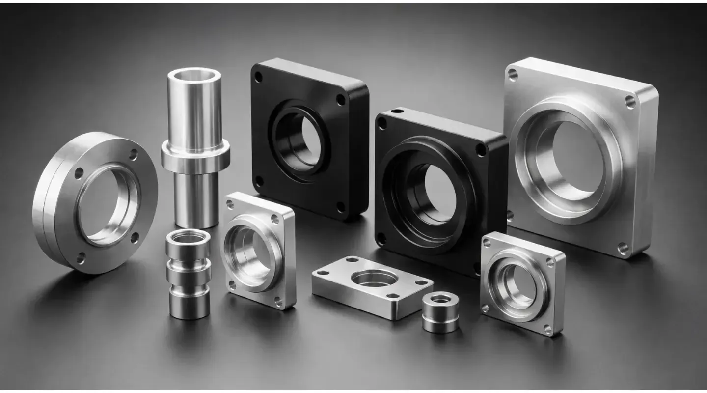
Optical Tube CNC Machining Case Study: How to Control Inner-Bore Tool Marks and Reduce Stray Light Interference
Why must the inner wall of an optical tube be free from visible tool marks, chatter marks, and scratches?
For an ordinary mechanical component, minor machining marks inside a bore may be treated as a cosmetic issue. However, for optical tubes, light baffles, lens barrels, and laser receiver housings, the inner-wall surface directly affects the performance of the optical system.
When light passes through an optical tube, tool marks, chatter patterns, fine scratches, and material tearing can create irregular reflective surfaces. These microscopic features may scatter light into the intended optical path and cause:
- Reduced image contrast;
- Increased glare or unwanted light spots;
- Interference with laser receiver signals;
- Lower signal-to-noise ratio in infrared systems;
- Unstable measurement results;
- Inconsistent optical performance between production batches.
For this reason, the inner-wall quality of an optical tube should not be judged only by whether it looks smooth. Measuring surface roughness at a single point is also insufficient.
A reliable machining solution must control the cutting tool, machining parameters, thin-wall deformation, deep-bore chip evacuation, and inspection method as one complete process.
This article uses a custom machining project for an overseas optical equipment manufacturer to explain:
- What causes inner-bore machining marks;
- How the machining process can be controlled;
- How samples should be validated;
- How overseas customers can evaluate an optical component CNC machining supplier.
What Causes Tool Marks Inside an Optical Tube?
Excessive Tool Overhang and Cutting Vibration
Optical tubes often have a relatively high length-to-diameter ratio. In some designs, the ratio between the machining depth and internal diameter exceeds 5:1.
During deep-bore machining, the boring tool must extend deep into the tube. The longer the tool overhang, the lower the overall rigidity and the greater the risk of vibration during cutting.
This vibration can produce regular wave patterns or chatter marks on the inner wall. Even when the height of these marks is only a few microns, they may still become a source of stray light under certain angles of incidence.
The machining supplier must therefore evaluate more than the final bore size. The following factors should also be controlled:
- Boring-bar diameter;
- Tool overhang length;
- Cutting-tool material;
- Spindle speed;
- Feed rate;
- Depth of cut;
- Machine rigidity;
- Fixture rigidity.
Poor Chip Evacuation
Optical tubes generally combine a relatively small internal diameter with a significant machining depth. This makes it difficult for chips to leave the bore naturally.
When chips remain between the cutting tool and the finished inner wall, they can be repeatedly compressed and dragged across the surface, leaving long scratches.
These scratches have several common characteristics:
- They may appear only in one section of the bore;
- They may not be detected by a standard surface roughness measurement;
- The complete inner surface may be difficult to inspect with the naked eye;
- They are usually more visible during borescope or optical inspection;
- They are more likely to occur during batch production than during prototype machining.
Chip removal must therefore be included in the CNC program rather than treated as a secondary production detail.
Entry, Exit, and Tool-Path Transition Marks
During conventional boring operations, the tool may leave transition marks when entering, retracting, changing direction, or repeating a cutting pass.
The actual height of these marks may be very small. However, local surface discontinuities can produce abnormal reflections inside an optical system.
When the drawing specifies requirements such as “no visible tool marks” or “no significant stray light,” the machining program should minimize:
- Repeated cutting passes;
- Unnecessary direction changes;
- Unstable tool retraction;
- Poorly positioned tool-path transitions;
- Sudden changes in cutting load during the final pass.
Machining Parameters Changed to Increase Output
Many suppliers can produce one acceptable prototype, but inner-wall quality becomes unstable when the order moves into small-batch production.
The problem is often not a sudden change in machine capability. It is usually caused by adjustments to previously validated production parameters, such as:
- Increasing the feed rate;
- Increasing the depth of cut;
- Extending tool replacement intervals;
- Reducing chip-blowing time;
- Removing the final finishing pass;
- Using a different tool brand or specification.
These changes may shorten the machining cycle, but they can also reduce surface consistency.
Overseas customers should therefore evaluate not only the prototype but also whether the supplier has controlled production parameters and a documented tool-life management system.
How Different Materials Affect Inner-Wall Quality
Common materials for optical tubes include aluminum alloys, stainless steel, and copper alloys. Each material has different cutting characteristics and requires a different process strategy.
6061-T6 Aluminum
6061-T6 is lightweight, relatively easy to machine, and widely used in optical equipment structures.
However, aluminum is relatively soft and can adhere to the cutting edge, creating a built-up edge. When the built-up material breaks away, it may cause:
- Surface tearing;
- Aluminum adhesion;
- Local roughness;
- Irregular bright marks;
- Fine scratches.
When machining a 6061-T6 optical tube, the supplier must pay particular attention to tool sharpness, friction, chip evacuation, and lubrication.
304 Stainless Steel
304 stainless steel has relatively low thermal conductivity. Cutting heat can become concentrated near the tool tip.
When the cutting edge is not sharp enough or the machining parameters are unsuitable, the following defects may occur:
- Work hardening;
- Rapid tool wear;
- Scale-like surface marks;
- Material tearing;
- Local heat discoloration.
Stainless steel optical tubes require stricter control of cutting temperature and tool condition.
Brass and Other Copper Alloys
Some copper alloys produce short, fragmented chips, making chip evacuation easier than with aluminum or stainless steel.
However, a worn cutting edge can still create compression marks and irregular bright bands on the inner wall.
Even for a relatively machinable material, the supplier should establish a defined tool-life standard.
Why Surface Roughness Alone Is Not Enough
Many optical component drawings only specify inner-wall surface roughness, such as:
- Ra ≤ 0.8 μm;
- Ra ≤ 0.4 μm;
- Ra ≤ 0.2 μm.
Surface roughness is important, but it does not fully represent the optical performance of the inner wall.
For example, a local scratch may not significantly affect the average reading from a surface roughness tester, but it may still generate a visible reflection under illumination.
Similarly, two components may have similar Ra values. However, if one has regular chatter marks and the other has a uniform surface, their stray-light performance may be different.
For optical tubes with light-transmission, light-blocking, or stray-light control requirements, the following inspection methods should be combined:
- Surface roughness measurement;
- Industrial borescope inspection;
- Visual inspection of critical areas;
- Light-transmission or stray-light testing;
- Batch inspection records;
- Tool-life and replacement records.
How to Select Cutting Tools for Optical Tube Machining
Carbide Tools
Carbide tools are widely available, reasonably economical, and suitable for many metal materials.
However, when machining aluminum, a carbide cutting edge with high friction or unstable sharpness may create built-up material, tearing, and inconsistent surface roughness.
Carbide tools can be suitable for rough machining or components with general surface requirements. For aluminum optical tubes with demanding inner-wall requirements, the final decision should be based on controlled test cutting.
CBN Tools
CBN tools offer high hardness and thermal resistance. They are mainly used for hardened steel, some cast irons, and other high-hardness materials.
For standard 6061-T6 aluminum optical tubes, CBN is generally not the preferred solution.
PCD Tools
PCD tools have a low coefficient of friction and good resistance to material adhesion. They are particularly suitable for aluminum alloys and certain non-ferrous metals.
When machining 6061-T6 aluminum optical tubes, PCD tools can help reduce:
- Built-up edge formation;
- Surface tearing;
- Roughness variation caused by tool wear;
- Surface inconsistency during batch production.
However, a PCD tool cannot solve every machining problem automatically.
If the boring bar lacks rigidity, the clamping method deforms the part, or the chip evacuation path is unsuitable, chatter marks and scratches may still occur.
The cutting tool is therefore only one part of the complete machining solution.
Key Process Controls for Deep-Bore, Thin-Wall Optical Tubes
Separate Rough and Finish Machining
The inner bore of an optical tube should generally not be machined to its final size in a single operation.
A more stable process may include:
- Rough machining;
- Semi-finishing;
- Deformation inspection or stress release;
- Finish machining;
- Final light finishing;
- Cleaning and inspection.
Rough machining removes most of the material, while finish machining controls the final dimensions and surface condition.
A staged process reduces cutting load and helps control both thin-wall deformation and tool vibration.
Control the Final Machining Allowance
If the finishing allowance is too large, the last pass will generate excessive cutting force. If it is too small, the finishing pass may not completely remove marks left by the previous operation.
The correct allowance depends on:
- Material;
- Internal diameter;
- Bore depth;
- Wall thickness;
- Boring-bar rigidity;
- Machine condition;
- Drawing roughness requirements.
Parameters from a different component should not be copied without validation.
Use a Low-Load Finishing Pass
After the main finishing operation, a low-load finishing pass may be added based on test results.
The purpose is not to remove a large amount of material, but to reduce residual machining marks and create a more uniform inner surface.
The finishing pass must still be carefully controlled.
If the tool has become dull, chips remain inside the bore, or the boring bar begins to vibrate, repeating the pass may create additional scratches rather than improve the surface.
Control Clamping Force on Thin Walls
When a thin-wall optical tube is clamped with standard hard jaws at high pressure, the component may become slightly oval during machining.
After the fixture is released, the component can spring back and create:
- Internal-diameter changes;
- Out-of-round conditions;
- Coaxiality deviation;
- Uneven wall thickness.
Depending on the design, suitable clamping methods may include:
- Custom soft jaws;
- Fixtures with a larger contact area;
- Supporting mandrels;
- Segmented clamping;
- Reduced clamping pressure;
- Inspection after unclamping.
The fixture should be designed around the component geometry rather than adjusted only through operator experience.
Add Chip-Evacuation Steps to the CNC Program
For deep internal bores, the CNC program may include:
- Programmed tool retraction;
- Compressed-air chip removal;
- Minimum-quantity lubrication;
- Dwell time for chip evacuation;
- Section-by-section machining;
- Auxiliary chip evacuation from the opposite end.
These operations add a small amount of machining time but can prevent costly scratches and batch rejection.
How to Select the Cooling and Lubrication Method
Flood Coolant
Cutting fluid helps reduce temperature, lubricate the cutting edge, and remove part of the chip load.
However, for optical components that later require cleaning, anodizing, bead blasting, or blackening treatment, residual cutting fluid and cleanliness must be considered.
Compressed-Air Cooling
Compressed air helps remove chips from the internal bore and reduces the risk of chips scratching the finished surface.
However, air alone offers limited lubrication and may not be suitable for every material or cutting condition.
Minimum-Quantity Lubrication
Minimum-quantity lubrication combines compressed air with a small amount of lubricant.
For certain deep-bore aluminum finishing applications, it can provide a practical balance between lubrication, chip evacuation, and post-machining cleaning.
The final method should be selected according to the material, bore geometry, cleaning requirements, and subsequent surface treatment.
Overseas Optical Equipment Customer Project
Project Background
TengRui Precision received an inquiry from an overseas optical equipment manufacturer.
The customer was developing an optical tube for a laser receiver module and required a supplier to manufacture prototypes and a subsequent small production batch from 2D drawings and a 3D model.
The primary requirements included:
- Material: 6061-T6 aluminum;
- Clear bore diameter: Ø18 mm;
- Component length: 85 mm;
- Wall thickness: 2 mm;
- Inner-wall roughness: Ra ≤ 0.4 μm;
- Clear-bore tolerance: ±0.02 mm;
- No visible tool marks, chatter, tearing, or scratches;
- Dimensional and surface-quality inspection records required with the samples.
The customer had already tested similar components from other suppliers.
Some suppliers could produce acceptable prototypes, but chatter marks and fine scratches began to appear during small-batch production.
The customer was not looking for a supplier that could occasionally produce one acceptable part. The real requirement was consistent inner-wall quality from the prototype stage through small-batch and future production.
Three Risks Identified During DFM Review
After receiving the drawings, the TengRui Precision engineering team conducted a design-for-manufacturing review.
Risk 1: Insufficient Rigidity Due to Long Tool Overhang
The bore diameter was only 18 mm, while the machining depth reached 85 mm.
The required boring-bar extension increased the risk of continuous chatter marks if a standard single-pass finishing process was used.
Risk 2: Deformation of the 2 mm Thin Wall
The wall thickness was only 2 mm. Excessive clamping pressure could deform the tube during machining.
If the bore were measured only while the component remained clamped, it could appear acceptable even though the internal diameter and roundness changed after unclamping.
Risk 3: Deep-Bore Chips Scratching the Inner Wall
If aluminum chips were not removed promptly, they could remain between the tool and the bore surface.
As machining continued, these chips could create long scratches on areas that had already been finished.
Process Investigation and Validation
The engineering team did not simply promise a “zero-tool-mark” result. Instead, it validated the main process variables affecting the inner-wall quality.
Tool Validation
To address aluminum adhesion, the engineering team compared standard carbide boring tools with PCD finishing tools.
A PCD boring tool suitable for aluminum finishing was selected to control built-up edge, surface tearing, and tool-wear variation during production.
Parameter Validation
Multiple cutting trials were conducted according to the boring-bar extension and internal geometry.
The trials focused on:
- Vibration at different spindle speeds;
- Surface patterns at different feed rates;
- Dimensional stability with different finishing allowances;
- Cutting load during the final pass;
- Surface changes after a light finishing pass.
The final parameters were established based on trial results and then locked for prototype and small-batch production.
Fixture Validation
Custom soft jaws were used to increase the clamping contact area and control pressure on the 2 mm wall.
After machining, the bore diameter and roundness were measured again in the unclamped condition to confirm the actual free-state dimensions.
Chip-Evacuation Validation
Programmed tool retraction and compressed-air cleaning were added to the finishing cycle.
Before the next finishing section began, residual aluminum chips were removed to prevent them from contacting the completed surface.
Final Machining Solution
Step 1: Use a PCD Finishing Tool
A PCD boring tool suitable for aluminum was selected.
After tool installation, radial runout and cutting-edge condition were checked. The tool was inspected for chipping, excessive wear, or aluminum adhesion before machining began.
Step 2: Use a Staged Machining Process
The production sequence included:
- Rough machining;
- Semi-finishing;
- Finish machining;
- Low-load light finishing;
- Cleaning;
- Inner-wall inspection.
A controlled finishing allowance was left after rough machining. Small depths of cut and stable feed rates were used during the finishing operations to reduce boring-bar vibration and thin-wall deformation.
Step 3: Add a Chip-Evacuation Cycle
After each specified machining section, the tool returned to a safe position and compressed air was used to remove chips from the bore.
The duration of the chip-clearing cycle was adjusted according to the bore depth and actual chip condition.
Step 4: Measure Roughness at Multiple Positions
Surface roughness was not measured at only one point.
Ra values were recorded at several axial positions to determine whether any local surface variation existed along the bore.
Step 5: Inspect the Complete Bore With a Borescope
After the roughness measurements, the full inner wall was inspected with an industrial borescope.
Special attention was given to:
- The tool-entry area;
- The tool-exit area;
- The middle of the deep bore;
- Tool-path transition areas;
- Locations where chips could accumulate;
- Local scratches, chatter, or surface tearing.
Prototype and First-Article Inspection
TengRui Precision first produced a trial component to validate the cutting tool, parameters, fixture, and chip-evacuation process.
After successful trial machining, the formal prototype and first-article inspection were completed.
The inspection covered:
- Inner-wall surface roughness;
- Bore dimensions at multiple axial positions;
- Bore roundness;
- Bore cylindricity;
- Coaxiality between the inner bore and external diameter;
- Critical wall thickness;
- Borescope inspection;
- Other critical dimensions specified on the drawing.
Electronic inspection records were sent to the customer for preliminary review, while the physical samples were shipped by international courier.
After assembly and optical performance testing, the customer approved the component for small-batch production.
Which Improvements Made the Difference?
PCD Tooling Reduced Aluminum Adhesion
The PCD tool reduced the risk of aluminum adhering to the cutting edge and helped produce a more uniform bore surface.
However, the tool could only perform effectively when combined with correct installation, stable parameters, and effective chip evacuation.
Staged Finishing Reduced Chatter Risk
Separating rough machining from finish machining prevented the final cutting pass from carrying excessive machining load.
A low-load finishing operation further reduced residual surface marks.
Custom Clamping Reduced Thin-Wall Springback
Soft jaws and controlled clamping pressure reduced the risk of compressing the tube into an oval shape.
Inspection after unclamping ensured that the measurement results represented the actual free-state condition of the component.
Programmed Chip Evacuation Reduced Production Scratches
Adding tool retraction and air cleaning increased the machining time slightly, but significantly reduced the risk of scratches during batch production.
A Closed Inspection Loop Improved Consistency
Combining surface roughness measurements, dimensional inspection, and borescope inspection identified defects that could be missed by a single inspection method.
The customer did not receive only one acceptable prototype. The customer received a repeatable manufacturing and inspection process that could be used for future production.
How to Verify a Supplier’s “No Visible Tool Marks” Claim
“No visible tool marks” is not a complete engineering specification.
Different customers may interpret this requirement differently. The inspection standard should therefore be clearly defined in the drawing or quality agreement.
Define Acceptable and Unacceptable Defects
The specification should clarify:
- Whether uniform finishing patterns are permitted;
- Whether minor local scratches are permitted;
- The maximum allowable scratch length and width;
- Whether tool-path transition marks are permitted;
- Whether the inner-wall appearance must be uniform;
- Whether blackening or light-absorbing treatment is required;
- Whether optical testing is required.
Define the Surface Roughness Measurement Locations
The drawing or inspection plan may specify:
- The number of axial measurement positions;
- The number of readings at each location;
- Whether only Ra or both Ra and Rz are required;
- Measurement direction;
- Probe type;
- Whether raw measurement records must be submitted.
Require Borescope Inspection
For small-diameter deep bores that cannot be completely observed with the naked eye, a borescope inspection is recommended.
A borescope can identify:
- Deep-bore scratches;
- Local chatter marks;
- Residual chips;
- Burrs;
- Surface tearing;
- Incomplete cleaning.
Determine Whether Stray-Light Testing Is Required
For general mechanical structures, roughness and visual inspection may be sufficient.
For lidar, infrared imaging, laser receiving, and high-precision measurement systems, an additional stray-light or optical test may be appropriate.
However, each optical system uses different wavelengths, incident angles, sensors, and internal geometries.
The test method should therefore be agreed upon by the customer and supplier before production rather than being defined by the supplier alone.
Frequently Asked Questions About Tool-Mark-Free Inner-Bore Machining
Q1: Is Ra 0.4 μm Sufficient to Eliminate Stray Light?
Not necessarily.
Whether Ra 0.4 μm is acceptable depends on the optical wavelength, angle of incidence, sensor sensitivity, internal geometry, and subsequent light-absorbing treatment.
Ra 0.4 μm may be acceptable for some optical structures. High-sensitivity laser, infrared, or measurement systems may require Ra 0.2 μm or a more demanding standard.
The final requirement should be determined by the customer’s optical design and actual test conditions.
Q2: How Should a Supplier’s “No Tool Marks” Claim Be Inspected?
At least two methods should be combined:
- Surface roughness measurements at multiple positions;
- Industrial borescope inspection.
For high-sensitivity optical systems, a light-transmission or stray-light test may also be required.
A single acceptable Ra measurement does not prove that the complete bore is free from scratches or chatter.
Q3: Why Can a Prototype Pass While a Small Batch Fails?
Common causes include:
- A new tool was used for the prototype;
- The tool became worn during batch production;
- The feed rate was increased to reduce cycle time;
- Chip-blowing time was reduced;
- A different tool brand or specification was used;
- Program parameters were changed by an operator;
- Clamping pressure varied between parts;
- The inspection frequency was insufficient.
The solution is to establish controlled parameters, a tool-life standard, and a batch first-article inspection process.
Q4: Does a Minor Inner-Bore Scratch Always Require Rejection?
Not always.
The decision depends on the scratch location, size, quantity, and actual optical test results.
A scratch located directly in the principal light path may increase stray light significantly. Multiple scratches may also create a larger cumulative effect.
If the drawing does not define a scratch standard, the customer and supplier should agree on a limit sample rather than relying only on a written description.
Q5: Are Walls Thinner Than 1.5 mm Likely to Deform?
Yes.
Thin-wall optical tubes are more sensitive to clamping force and cutting load.
The supplier may need to evaluate:
- Custom soft jaws;
- Internal supporting mandrels;
- Staged machining;
- Reduced depth of cut;
- Controlled clamping pressure;
- Intermediate stress release;
- Inspection after unclamping.
The final process depends on the material, length, diameter, and structural design.
Q6: What Should Be Done When the Drawing Specifies Roughness but No Optical Requirement?
The requirement should be confirmed during the quotation stage.
The supplier may ask:
- Is the component located in the active optical path?
- Is stray-light control required?
- Is black anodizing or another light-absorbing treatment required?
- Is borescope inspection required?
- Is a light-transmission or stray-light test required?
- Is a reference or limit sample available?
Confirming these points early helps prevent disagreement after the prototypes have been manufactured.
How to Evaluate an Optical Tube CNC Machining Supplier
The challenge of optical tube machining is not limited to dimensional accuracy. It also involves inner-wall condition, production consistency, and a complete inspection process.
Overseas customers can evaluate a supplier by reviewing the following areas.
Does the Supplier Perform DFM Review?
The supplier should analyze:
- Length-to-diameter ratio;
- Thin-wall deformation;
- Tool accessibility;
- Tolerance feasibility;
- Surface roughness;
- Inspection feasibility;
- Surface-treatment risks.
A supplier that provides an immediate quotation without discussing manufacturing risks may simply be postponing the problems until prototype or production.
Does the Supplier Have Deep-Bore Machining Experience?
Customers can ask:
- Which cutting tool will be used?
- How will long-tool vibration be controlled?
- How will chips be removed?
- How will thin-wall deformation be prevented?
- Will soft jaws or a supporting mandrel be used?
- Has the supplier machined components with a similar length-to-diameter ratio?
Can the Supplier Provide a First-Article Inspection Report?
A first-article inspection report should cover:
- Internal diameter;
- Roundness;
- Cylindricity;
- Coaxiality;
- Critical wall thickness;
- Surface roughness;
- Other critical drawing dimensions.
Can the Supplier Perform Borescope Inspection?
For a small-diameter deep bore, visual inspection alone may not reveal the complete inner-wall condition.
Customers should confirm:
- Whether the supplier has an industrial borescope;
- Whether photographs or videos can be saved;
- The inspection frequency during batch production;
- How long inspection records are retained.
Does the Supplier Manage Cutting-Tool Life?
Tool-life management directly affects production surface quality.
Customers can ask whether the supplier records:
- Tool identification;
- Number of components machined;
- Tool-wear condition;
- Mandatory replacement interval;
- First-piece and in-process inspection results.
Can the Supplier Support Overseas Documentation Requirements?
International OEM projects may also require:
- English inspection reports;
- Material certificates;
- Surface-treatment certificates;
- Custom packaging;
- International shipping;
- NDA confidentiality agreements;
- Engineering change records;
- Drawing revision control.
A suitable supplier must be able to support both manufacturing and the complete international project workflow.
TengRui Precision Optical Tube CNC Machining Services
TengRui Precision Machinery Co., Ltd. is a China-based CNC machining supplier providing custom OEM precision manufacturing services to overseas customers.
Components are manufactured according to customer-supplied 2D drawings, 3D models, and technical specifications. TengRui Precision does not sell standard off-the-shelf optical tubes.
Our services cover:
- One-piece prototypes;
- Engineering validation samples;
- Low-volume production;
- Mass production;
- CNC turning;
- CNC milling;
- Five-axis CNC machining;
- Surface finishing;
- Dimensional and surface roughness inspection;
- International shipping.
DFM Review Before Production
Before production begins, our engineering team can evaluate:
- Material machinability;
- Bore length-to-diameter ratio;
- Internal tool accessibility;
- Boring-bar rigidity;
- Thin-wall deformation risk;
- Surface roughness requirements;
- Coaxiality and roundness requirements;
- Clamping datums;
- Surface-treatment allowance;
- Inspection methods.
When a possible conflict exists between the component design and manufacturing stability, our engineers will explain the risk and provide manufacturing recommendations.
The customer’s design will not be modified without written approval.
Minimum Order Quantity of One Piece
TengRui Precision supports orders starting from one piece, making the service suitable for:
- New product development;
- Structural validation;
- Optical module testing;
- Supplier capability evaluation;
- Low-volume market testing;
- Replacement-part manufacturing.
After prototype approval, production can continue using the validated process for small or larger batches.
Optical Components We Can Evaluate
Based on customer drawings, we can evaluate the machining of:
- Optical tubes;
- Light baffles;
- Lens barrels;
- Focusing sleeves;
- Laser equipment components;
- Lidar components;
- Infrared equipment components;
- Optical measurement instrument parts;
- Sensor housings;
- Detector housings;
- Deep-bore thin-wall components;
- High-coaxiality sleeves;
- Precision internal-bore components.
Materials We Machine
Common materials include:
- 6061 aluminum;
- 6063 aluminum;
- 7075 aluminum;
- 304 stainless steel;
- 316L stainless steel;
- Brass;
- Copper alloys;
- PEEK;
- POM;
- Other machinable engineering materials.
The final material and machining process are evaluated according to the customer’s drawing and application environment.
Inspection and Quality Control
Depending on the project requirements, we can provide:
- First-article inspection reports;
- CMM inspection;
- Surface roughness measurements;
- Internal-diameter inspection;
- Roundness inspection;
- Coaxiality inspection;
- Borescope inspection;
- Material certificates;
- Surface-treatment records;
- Critical-dimension measurement records.
For components with light-transmission, light-blocking, or stray-light control requirements, we can evaluate the feasibility of supporting a customer-defined test method.
Support for Overseas Projects
Overseas customers can send the following files and information by email:
- PDF engineering drawings;
- STEP or STP models;
- IGES models;
- X_T models;
- Required quantities;
- Material specifications;
- Surface-treatment requirements;
- Inspection standards;
- Target delivery date.
After project confirmation, prototypes can be shipped by DHL or another international courier.
Inspection reports and project documents can be provided electronically.
Drawing and Project Confidentiality
Customer drawings, 3D models, and technical documents are used only for quotation, engineering review, production, and inspection.
When confidentiality is required, TengRui Precision can sign an NDA before the customer submits the complete design package.
Without customer authorization, we will not disclose:
- Product drawings;
- 3D models;
- Product structures;
- Brand logos;
- Project names;
- Inspection data;
- Purchasing information.
Which Optical Tube Projects Are Suitable for TengRui Precision?
You may submit your drawings for evaluation when your project includes one or more of the following requirements:
- No visible tool marks on the inner wall;
- Inner-wall roughness of Ra ≤ 0.4 μm or tighter;
- A length-to-diameter ratio greater than 5:1;
- A deep-bore, thin-wall structure;
- Tight roundness and coaxiality requirements;
- Acceptable prototypes but unstable batch surface quality;
- Repeated scratches from an existing supplier;
- A first-article inspection report;
- Borescope inspection records;
- English inspection documentation;
- A prototype quantity starting from one piece;
- Subsequent low-volume or production orders.
Information to Prepare Before Requesting a Quotation
To receive a more accurate quotation, process evaluation, and lead-time estimate, customers should provide:
- A 2D engineering drawing;
- A 3D model;
- The material grade;
- Prototype and production quantities;
- Inner-wall roughness requirements;
- Dimensional and geometric tolerances;
- Surface-treatment requirements;
- Whether borescope inspection is required;
- Whether light-transmission or stray-light testing is required;
- Whether FAI or CMM reports are required;
- The target delivery date;
- The international shipping destination.
If the drawing includes any of the following notes, they should also be highlighted in the inquiry email:
- No visible tool marks;
- No chatter marks;
- No scratches on the inner bore;
- Ra ≤ 0.2 μm;
- Stray light control;
- Black anodizing;
- Optical black coating;
- Full inner-wall borescope inspection.
Conclusion
The challenge of optical tube machining is not simply keeping the internal diameter within tolerance.
The final project result also depends on:
- Whether the inner-wall surface is uniform;
- Whether local tool marks or scratches are present;
- Whether the thin-wall component springs back after machining;
- Whether the prototype and production batch use the same process;
- Whether cutting-tool life is controlled;
- Whether the complete inner wall is properly inspected;
- Whether the inspection records are traceable.
For overseas optical equipment manufacturers, supplier selection should not be based only on one prototype or the lowest unit price.
A more important question is whether the supplier can establish a complete process covering DFM review, test cutting, first-article inspection, and batch production control.
If you are developing an optical tube, light baffle, lens barrel, focusing sleeve, or another deep-bore thin-wall optical component, you can send your 2D drawing, 3D model, material, quantity, and inspection requirements to TengRui Precision.
Our engineering team will evaluate the machining risks, recommended process, inspection method, and estimated lead time before production begins.