
Aug 21, 2026
CNC Machining for Precision Humanoid Robot Parts | Supplier Guide
Learn how to evaluate a CNC machining supplier for humanoid robot parts, including AGV chassis frames, joint housings, reducer flanges, thin-wall parts, and precision bearing components.
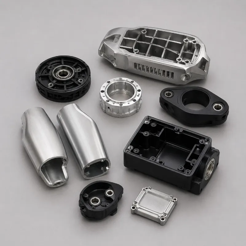
When a mechanical engineer sends an AGV chassis frame, robot joint housing, or reducer flange drawing to a CNC machining supplier, one of the least useful answers is:
“We can make it.”
A drawing requirement such as flatness ≤0.1 mm over 500 mm or position tolerance ≤0.05 mm cannot be guaranteed by a verbal promise.
The greater risk is often not that the supplier completely fails to produce the prototype. The prototype may pass inspection, but after production increases to 20, 50, or 100 parts, critical dimensions begin to drift.
The customer may then discover:
- Mounting surfaces are no longer flat
- Bearing bores are not properly aligned
- Hole patterns do not fit the assembly
- Thin walls deform after unclamping
- Surface treatment changes critical fitting dimensions
- Supplier and customer inspection results do not agree
For an overseas customer, these problems can result in replacement production, additional air freight, engineering delays, and missed robot development schedules.
Choosing a CNC machining supplier for precision humanoid robot components is therefore not simply about finding a factory with CNC machines. It is about finding a supplier that can understand the drawing, identify manufacturing risks before production, and verify process stability before volume increases.
Why Precision Robot Parts Are Difficult to Machine
Humanoid robot components are different from ordinary industrial hardware.
Joint housings, reducer flanges, bearing housings, motor mounts, and AGV chassis frames may combine several challenging characteristics:
- Large overall dimensions
- Thin-wall sections
- Multiple mounting surfaces
- Tight hole-position tolerances
- Concentric bearing and locating features
- Complex datum relationships
- Anodizing or other post-machining finishes
These features interact with each other. A change in one surface or bore may affect the alignment of the complete robot joint.
For example, a 6061-T6 aluminum AGV chassis frame may need to support motors, reducers, sensors, and other modules. Its drawing may specify overall flatness within 0.1 mm over 500 mm and position tolerances within 0.05 mm for multiple mounting features.
The challenge is not only whether the machine has sufficient travel. The supplier must also determine:
- How the part will be clamped
- How machining stress will be balanced
- How roughing and finishing will be separated
- Which features should share the same datum
- How the part will be measured after unclamping
- How finishing will affect final dimensions
If a large thin aluminum frame is pressed flat with conventional clamps and then machined, it may appear flat while it remains fixed to the machine table. Once the clamps are released, the part may spring back and become distorted.
This is why machining should begin with a Design for Manufacturing review, not with the machine cycle.
What Should Be Checked During DFM?
A practical DFM review for a robot component should evaluate:
- Material grade and supply condition
- Wall thickness and structural rigidity
- Areas at risk of clamping deformation
- Features that may drift during batch production
- Machining and inspection datums
- Tool access
- Fixture and support requirements
- Residual material stress
- Surface treatment allowances
- Inspection feasibility
For a large component with a demanding flatness requirement, the process may require staged roughing to remove most of the material, followed by intermediate stabilization and final machining with a smaller depth of cut.
The exact process depends on the part geometry and material condition.
Flatness of 0.1 mm over 500 mm means that the difference between the highest and lowest measured points across that area cannot exceed 0.1 mm.
Machine accuracy alone cannot guarantee this result. Fixture design, tool paths, cutting forces, residual stress, temperature, and inspection methods all affect the final measurement.
Before approving a supplier, ask:
- How will the part be clamped and supported?
- Will roughing and finishing be separated?
- How will spring-back after unclamping be controlled?
- Which critical surfaces will share the same datum?
- How will flatness and position be inspected?
A supplier that can answer these questions based on the actual drawing is more valuable than one that only provides a long equipment list.
How Thin-Wall Deformation Can Be Controlled
Thin-wall AGV frames, robot joint housings, reducer housings, and other lightweight structural parts can deform for three main reasons.
1. Clamping Deformation
Excessive clamping force can distort a thin component during machining. When the fixture is released, the part returns toward its original shape, changing the final dimensions.
Insufficient clamping force creates a different risk: vibration or movement during cutting.
Depending on the part, the solution may involve:
- Custom soft jaws
- Additional support points
- Low-stress fixtures
- Controlled clamping force
- Vacuum workholding where appropriate
Vacuum workholding is not automatically suitable for every thin-wall component. The available sealing area, cutting direction, machining force, and part geometry must all be considered.
2. Cutting-Force Deformation
A thin wall can move away from the cutting tool under load. This is often called tool push-off or part deflection.
After the tool passes, the wall springs back, leaving a dimension that differs from the programmed value.
Possible control methods include:
- Reducing the depth of cut
- Limiting radial cutting force
- Using multiple semi-finishing operations
- Optimizing the tool path
- Selecting sharp tools suitable for the material
- Avoiding excessive localized heat
- Leaving a uniform finishing allowance
Cutting parameters should be selected according to the material, tool, machine, wall thickness, and geometry. A fixed set of parameters should not be applied to every thin-wall component.
3. Residual-Stress Deformation
Rolled aluminum plate, extrusions, and forgings can contain different levels of residual stress.
When large amounts of material are removed, the original stress balance changes. The part may then distort during machining or several hours after machining is complete.
Depending on the project, the supplier may need to consider:
- Stress-stable raw material
- Separate roughing and finishing
- Natural aging after roughing
- Stress-relief treatment where necessary
- Re-establishing the datum before finishing
- Symmetrical material removal
The most important point is not whether the supplier uses one specific technique. It is whether the supplier understands the source of deformation and can propose a process that matches the drawing.
Control Area | Customer Concern | What the Supplier Should Explain |
|---|---|---|
Workholding | Will clamping distort the part? | Clamping locations, support points, and force control |
Tool path | Will the wall deflect during cutting? | Layered cutting, semi-finishing, and finishing strategy |
Stress control | Will the part move after machining? | Material condition, aging, or stress-relief plan |
Inspection | Can the results be trusted? | CMM method, flatness measurement, and report scope |
How to Control Threads, Concentricity, and Position Tolerances
Robot joint components may contain precision threads, bearing bores, locating pilots, hole patterns, and splines.
These features depend on their relationship to one another. If the machining datum changes between operations, errors can accumulate.
Consider a reducer flange containing a shaft feature, locating pilot, and circular mounting-hole pattern. If these features are produced in separate setups without a stable common datum, concentricity and position may become difficult to control.
A lower-risk process may include:
- Machining related features in one setup where practical
- Maintaining a repeatable datum when multiple setups are necessary
- Aligning machining and inspection datums
- Verifying the dimensional chain during FAI
- Monitoring critical features during pilot production
TengRui Precision operates 3-axis, 4-axis, and 5-axis CNC machining equipment. When several critical features are related by concentricity or position, our engineering team evaluates whether five-axis machining or another consolidated process can reduce repeated setups.
However, five-axis equipment does not automatically guarantee accuracy. Fixture stability, datum control, tooling, programming, and inspection remain essential.
Precision Threads Require More Than a Fit Check
For standard threaded holes, tapping may be appropriate. For threads with demanding accuracy, alignment, material, or repeatability requirements, thread milling may provide better process control.
Inspection should be based on the drawing and may include:
- Go/no-go thread gauges
- Thread class verification
- Pitch diameter requirements
- Alignment with related features
- Profile or other special inspection where required
“Both parts can be screwed together” is not sufficient evidence for a precision thread used in a critical robot assembly.
Prototype Accuracy Does Not Prove Batch Stability
Humanoid robot projects often begin with single parts or small batches and then change quickly as the design develops.
In this environment, a supplier’s ability to support fast prototyping is useful. However, speed should not replace process validation.
A reasonable prototype-to-production process is:
Stage | Main Purpose | Expected Evidence |
|---|---|---|
DFM review | Identify manufacturing and inspection risks | DFM feedback and open questions |
First article | Verify the complete drawing | FAI report |
Pilot batch | Evaluate repeatability | Consecutive-part data or CPK |
Production preparation | Standardize machining and inspection | Agreed control documents |
A prototype proves that one part can be produced.
A pilot batch helps determine whether the same result can be repeated as tools wear, machines warm up, fixtures are reloaded, and material batches change.
For important production dimensions, CPK ≥1.33 is commonly used as a process-capability reference. The required value, sample size, and measurement method should be agreed upon before production.
Overseas customers should also remember that lead time includes more than machining. Material sourcing, finishing, inspection, packaging, and international transportation must all be included in the project schedule.
Skipping DFM or full first-article inspection may save one or two days at the beginning but create weeks of delay if the parts fail after delivery.
Five Criteria for Evaluating a Robot Parts Supplier
1. Ask for Evidence From Similar Parts
If a supplier claims experience with joint housings, reducer flanges, or bearing housings, request non-confidential examples such as:
- Similar-part photographs
- Sample inspection reports
- Materials and approximate part sizes
- Critical tolerances controlled
- Inspection equipment used
- Pilot-production data
This evidence is more useful than a general statement about years of machining experience.
2. Evaluate DFM Capability
After receiving the drawing, does the supplier immediately send a price, or first ask questions about the material, wall thickness, datum system, tolerances, finishing, and inspection?
A supplier that identifies potential problems before production can help reduce the customer’s trial-and-error cost.
3. Verify Inspection Capability
An FAI report should include actual measurements for critical dimensions and geometric tolerances.
For flatness, position, and concentricity requirements, confirm that the supplier has suitable CMM capability and that its inspection datum matches the drawing.
TengRui’s quality department is equipped with Zeiss and Hexagon coordinate measuring machines, as well as Mitutoyo surface roughness measuring equipment.
The required inspection scope should always be confirmed during quotation.
4. Confirm Small-Batch Support
Some suppliers accept one prototype but are less willing to support a 20-piece or 50-piece pilot batch.
However, pilot production is where tool wear, fixture repeatability, material deformation, and finishing consistency become visible.
Validating the process before increasing order quantities helps reduce inventory, rework, replacement, and international freight risks.
5. Check Traceability and Quality Management
A quality system should provide more than a certificate.
Buyers should confirm:
- Whether raw materials are traceable
- How drawing revisions are controlled
- Whether inspection reports match production batches
- How nonconforming parts are isolated
- Whether process changes require customer approval
- How root-cause and corrective-action reports are handled
TengRui operates under an ISO 9001 quality management system.
If a project requires FAI, SPC, CPK, material certificates, or customer-specific documents, the scope should be defined during the RFQ stage. PPAP or other industry-specific documentation should also be confirmed rather than assumed to be included in every order.
How TengRui Supports Overseas Robotics Projects
TengRui Precision has provided custom CNC machining services for overseas business customers since 2006.
Our manufacturing resources include more than 80 precision machines, covering 3-axis, 4-axis, and 5-axis machining, CNC turning, grinding, and wire EDM. Twenty of these machines are five-axis machining centers.
These capabilities provide the manufacturing foundation, but they do not replace project-specific validation.
For the customer, the important questions remain:
- Has the drawing received a complete DFM review?
- Is there a practical process for every critical tolerance?
- Does the inspection method match the drawing?
- Will the prototype include an FAI report?
- Has repeatability been checked in a pilot batch?
- Will critical dimensions be rechecked after finishing?
- Is the packaging suitable for international transportation?
For a new robot component, a lower-risk approach is to begin with one prototype or a small pilot batch. The machining results, inspection data, and actual assembly performance can then be reviewed before production quantities increase.
The purpose is not to create additional steps. It is to control the customer’s risk before committing to larger inventories, international freight, and full production schedules.
Frequently Asked Questions
How can thin-wall deformation in humanoid robot parts be controlled?
Thin-wall deformation may result from clamping force, cutting force, cutting heat, and residual material stress.
Control methods may include low-stress workholding, additional support, staged material removal, separate roughing and finishing, small finishing cuts, and intermediate aging or stress relief where required.
The process should be developed from the actual drawing and verified through prototype and pilot-production measurements.
Can a CNC supplier achieve flatness of 0.1 mm over 500 mm on an AGV chassis frame?
The requirement may be achievable, but feasibility depends on the part size, material condition, wall thickness, fixture design, machining sequence, and inspection method.
Machine accuracy alone is not enough. Request a DFM review and verify the result through a complete FAI report. For production, consecutive-part data should also be reviewed.
How long does prototype machining for humanoid robot parts take?
A conventional prototype may take approximately 3–7 working days, while a small pilot batch may require 7–15 working days.
Actual lead time depends on material availability, complexity, tolerances, finishing, inspection, and quantity.
Providing both a PDF drawing and STEP model—with material, critical tolerances, finishing, inspection, and delivery requirements clearly defined—helps the supplier provide a more accurate quotation and schedule.
What should be included in an RFQ for precision robot components?
A complete RFQ should include:
- Dimensioned PDF drawing
- STEP model
- Material grade and condition
- Prototype and production quantities
- Critical dimensions and geometric tolerances
- Surface treatment requirements
- Inspection and documentation requirements
- Packaging instructions
- Delivery location and Incoterms
Incomplete technical information usually results in a preliminary quotation that may change later.
Do Not Ask Only “Can You Make It?”
When evaluating a CNC machining supplier for humanoid robot parts, the final decision comes down to two questions:
- Can the supplier manufacture the part according to the drawing?
- Can the supplier maintain the critical dimensions during batch production?
The first question should be verified through DFM and FAI.
The second should be verified through pilot production, consecutive measurement data, and process control.
For overseas buyers, the real cost is not limited to the quoted unit price. It also includes assembly failures, engineering time, replacement production, international shipping, and project delays.
If you are developing an AGV chassis frame, robot joint housing, reducer flange, bearing housing, motor mount, or another precision robotics component, begin with a drawing review.
Send the PDF drawing and STEP model, then confirm the material, tolerances, datum system, workholding, surface treatment, inspection, and packaging requirements before machining starts.
A verified prototype and pilot batch usually cost far less than discovering the problem after an entire production order has crossed the border.
Contact TengRui Precision for a DFM review and quotation for your custom humanoid robot components.