
Jul 25, 2026
Robot Parts with 0.005 mm Tolerances
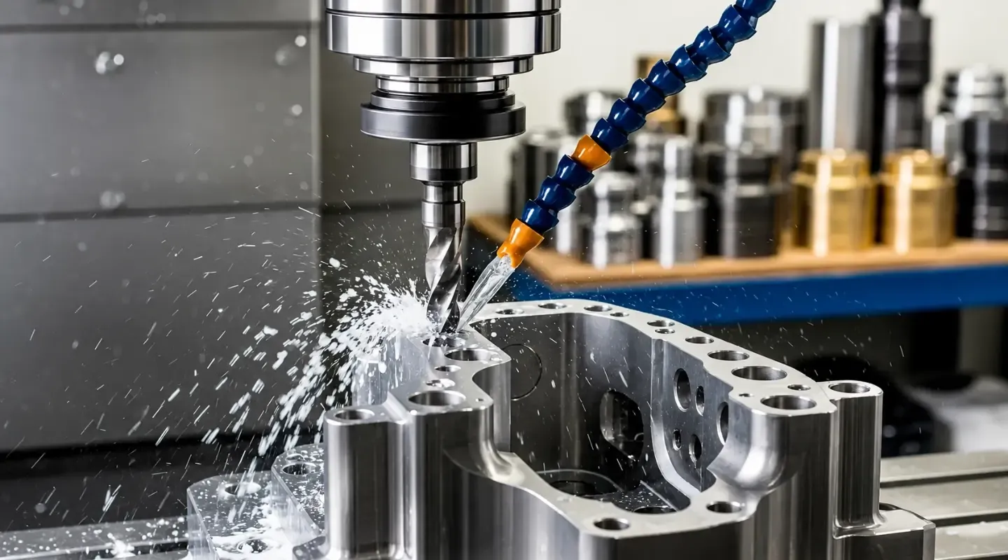
How to Choose a CNC Manufacturer for Robot Parts with 0.005 mm Tolerances
Robot components such as robotic arm joints, gearbox flanges, bearing housings, and servo motor housings often involve more than basic dimensional tolerances. They may also require tight control of concentricity, position, flatness, perpendicularity, and surface roughness.
A tolerance of 0.005 mm may look like only a few microns on a drawing. However, in robotic joint assembly, those few microns can directly affect bearing installation, rotational resistance, joint repeatability, and the operating stability of the complete system.
Many engineers have encountered the same problem: a supplier claims that it can machine to 0.005 mm, but the first article still shows deviations in critical bores or mating features. The part may appear acceptable during a visual inspection, yet bearing installation becomes difficult, rotation feels uneven, clearances vary, or operating noise increases during assembly.
For this reason, selecting a CNC manufacturer for robot parts should not be based only on price or machine photos. Buyers also need to confirm whether the supplier has reliable process-planning capabilities, precision inspection equipment, and a complete quality-control system.
This article explains why 0.005 mm tolerances are difficult to maintain on robot parts, what capabilities a qualified supplier should have, and what overseas customers should verify before choosing a CNC machining partner.
Why is a 0.005 mm Tolerance Difficult to Maintain on Robot Parts?
Precision problems in robot components are rarely limited to one diameter or one linear dimension.
What affects assembly and operating performance is often the relationship between several critical features, including:
- Concentricity between two bearing bores
- Perpendicularity between a bearing bore and a mounting face
- True position between motor mounting holes and gearbox mounting holes
- Parallelism between multiple mounting surfaces
- Roundness of a machined bearing seat
- Final mating dimensions after surface treatment
Consider a robotic arm joint housing. Even when the diameter of each individual bearing bore falls within tolerance, the bearings may still experience misalignment, binding, or premature wear when the two bore axes are not properly aligned.
Therefore, being able to machine a dimensional tolerance of ±0.005 mm does not automatically mean that a manufacturer can maintain geometric tolerances at the same level.
1. Multiple Setups Create Accumulated Errors
Joint housings, gearbox housings, and servo motor housings commonly include holes, pockets, mounting faces, and other features in multiple directions.
When these features are produced on a conventional 3-axis machine, the part may need to be repositioned and reclamped several times. Every new setup introduces another opportunity for datum-transfer and positioning errors.
These errors may remain acceptable for general-purpose parts. However, when the critical tolerance is only 0.005 mm, accumulated setup errors can quickly cause concentricity or positional tolerances to fall outside the drawing requirements.
2. Thin-Walled Structures Are Easily Deformed
Robot housings are often designed with thin walls, reinforcing ribs, and complex internal cavities to reduce weight while maintaining stiffness.
After a large amount of material is removed during rough machining, residual stress inside the raw material may be redistributed. Without a suitable sequence for rough machining, semi-finishing, stress relief, and final finishing, the part may deform slightly during machining or after it is removed from the fixture.
This deformation may not be significant for general tolerances, but a change of only a few microns can affect a 0.005 mm requirement.
3. Tool Wear Causes Dimensional Drift During Batch Production
Producing one acceptable first article does not guarantee that every subsequent part will remain within tolerance.
As the cutting tool continues to operate, tool-tip wear, spindle temperature, and cutting conditions change. If a supplier checks only the first article and does not implement in-process inspection or tool-offset control, critical dimensions may gradually drift during batch production.
4. Temperature Changes Affect Machining and Measurement
Differences in temperature between the part, measuring equipment, and inspection environment can cause materials to expand or contract.
This effect may be negligible for a general tolerance of ±0.1 mm. However, it must be considered when machining and measuring dimensions or geometric tolerances at the 0.005 mm level.
A high-precision part must not only be machined accurately. It must also be verified under stable and appropriate inspection conditions.
5. Conventional Measuring Tools Cannot Fully Verify Geometric Tolerances
Calipers, micrometers, and bore gauges are useful for measuring lengths, diameters, and thicknesses. However, they cannot fully verify concentricity, true position, profile, or complex spatial relationships.
For robot joint housings and similar parts, checking only with handheld measuring tools is insufficient. Critical geometric tolerances usually need to be verified with a coordinate measuring machine.
How Does TengRui Evaluate Robot Parts with 0.005 mm Requirements?
TengRui provides made-to-drawing OEM manufacturing services.
After receiving the customer's 2D drawings, 3D models, material specifications, quantities, and finishing requirements, our engineering team conducts a manufacturability review before production begins.
The review normally covers the following points:
- Which specific dimensions or geometric tolerances require 0.005 mm control
- Which datums are used for the critical features
- Whether critical features can be completed in a single setup
- Whether thin walls may deform under clamping pressure
- Whether residual stress may be released after material removal
- Whether the surface treatment will change final dimensions
- Which inspection equipment will be used to verify the requirements
- Whether the specified tolerances are appropriate for the part's function and target cost
It is important to understand that 0.005 mm is not a universal capability that can be guaranteed for every material, part size, or geometry.
The achievable tolerance must be evaluated according to the part dimensions, material, structural design, clamping method, surface treatment, and inspection method. For critical projects, completing first-article verification before moving into pilot or volume production is recommended.
Three Key Controls for 0.005 mm Robot Parts
1. Reduce Repeated Setups for Critical Features
For robot components with precision requirements in multiple directions, the main value of 5-axis machining is not simply faster production. It is the ability to reduce part repositioning and repeated clamping.
Where the geometry allows, several critical bores, mounting faces, and profiles can be machined from one datum in a single setup. This reduces accumulated errors caused by datum transfers.
TengRui is equipped with 3-axis, 4-axis, and 5-axis CNC machining equipment. According to our company profile, the machining department includes approximately 40 3-axis machines, 40 4-axis machines, and 20 5-axis machines. The appropriate machining method is selected according to the part geometry and tolerance requirements.
Five-axis machining is commonly suitable for parts such as:
- Robotic arm joint housings
- Gearbox mounting flanges
- Servo motor housings
- End-effector housings
- Robotic link components
- Parts with holes in multiple directions
- Complex surfaces and lightweight structural components
However, not every part with a 0.005 mm tolerance requires 5-axis machining.
For shafts, sleeves, and rotational components with relatively simple structures, precision CNC turning, 4-axis machining, or dedicated fixtures may also provide stable results.
The machine type alone does not determine the final accuracy. What matters is whether the process plan can control the datums, clamping forces, and accumulated setup errors.
2. Control Tool Wear and Material Deformation
High-precision machining cannot depend only on the positioning accuracy of the machine tool.
The engineering team must also plan and control:
- Roughing and finishing sequences
- Appropriate machining allowance
- Tool overhang
- Cutting parameters
- Condition of finishing tools
- Tool-life management
- Clamping methods for thin-walled areas
- Necessary in-process inspections
- Dimensional verification after the part is released from the fixture
For thin-walled robot housings, material can first be removed evenly during rough machining while leaving a suitable finishing allowance. This gives residual stress an opportunity to redistribute before final machining.
Bearing seats, precision mounting faces, and critical locating holes should be completed under stable datum and cutting conditions. Final finishing should be avoided when part rigidity is insufficient or when thermal variation is not adequately controlled.
3. Create a Closed-Loop Inspection Process
After machining, the supplier must be able to verify the drawing requirements with suitable inspection equipment.
TengRui's quality department is equipped with Zeiss and Hexagon coordinate measuring machines, a Mitutoyo surface roughness tester, and height-measuring equipment. Some of the Hexagon CMM equipment listed in the company profile has a stated measurement accuracy of approximately 1.9 μm and can be used to inspect critical dimensions and geometric tolerances.
Typical inspection items for precision robot parts include:
Inspection item | Main purpose | Typical inspection method |
|---|---|---|
Bore and shaft diameters | Confirm bearing, bushing, and sealing fits | Bore gauge, micrometer, CMM |
Concentricity | Confirm that multiple bearing bores share the required axis | Coordinate measuring machine |
True position | Verify mounting-hole and locating-hole positions | Coordinate measuring machine |
Flatness | Confirm stable contact between mounting surfaces | CMM or suitable flatness inspection equipment |
Perpendicularity and parallelism | Verify the relationship between assembly datums | Coordinate measuring machine |
Surface roughness | Confirm friction, sealing, and appearance requirements | Surface roughness tester |
Threads | Confirm reliable fastening and assembly | Thread plug gauges and ring gauges |
Appearance | Check for dents, scratches, and finishing defects | Visual inspection and approved samples |
TengRui's production process includes both in-process and final inspection. Parts are inspected before shipment, and inspection documentation can be provided according to the customer's project requirements.
A Typical Workflow for an Overseas Robot-Part Project
For international robotics and automation customers, communication costs, transportation time, and repeated sampling expenses are higher than those involved in local sourcing.
Project success therefore depends heavily on whether the supplier can identify manufacturing risks before machining and provide sufficient quality information before shipment.
A typical TengRui overseas OEM project follows the process below.
Step 1: The Customer Submits the Drawings and Requirements
The customer should provide:
- 2D engineering drawings
- 3D models
- Material grade
- Estimated quantity
- Surface-treatment requirements
- Critical dimensions and special characteristics
- Target lead time
- Inspection-report requirements
When drawing confidentiality is required, a non-disclosure agreement can be signed before complete design files are submitted.
Step 2: The Engineering Team Conducts a DFM Review
The engineering team checks whether the part is suitable for the proposed manufacturing process and confirms:
- Whether the tolerances are manufacturable
- Whether any requirements are difficult or impossible to inspect
- Whether the machining datums are clearly defined
- Whether thin-walled areas may deform
- Whether surface-treatment compensation is required
- Whether dedicated fixtures are necessary
- Whether first-article or pilot-batch verification is recommended
The supplier should not change the product design without the customer's written approval.
Step 3: Quotation and Production Planning Are Confirmed
The quotation is normally affected by:
- Raw material
- Machining time
- Number of setups
- Tools and fixtures
- Inspection requirements
- Surface treatment
- Quantity
- Packaging and shipping method
For parts with 0.005 mm requirements, the cost of inspection and process control is normally higher than it is for general-tolerance parts.
When comparing quotations, buyers should therefore confirm whether every supplier is quoting against the same manufacturing, inspection, and quality-documentation requirements.
Step 4: First-Article Machining and Inspection
For critical robot components, first-article production is recommended before batch manufacturing.
After the first article is completed, all critical dimensions and geometric tolerances should be inspected according to the drawing. The customer can request the first-article inspection results before approving further production.
First-article approval confirms more than whether the supplier can machine one acceptable part. It also helps verify:
- Whether the machining datums are appropriate
- Whether the clamping method is stable
- Whether the measurement method is consistent
- Whether the surface-treatment allowance is correct
- Whether the process can be repeated during batch production
Step 5: Pilot-Batch or Volume Production
After first-article approval, the project can proceed to pilot-batch verification or formal production.
During production, appropriate in-process checks should be scheduled according to the critical dimensions, tool life, and process stability. This helps prevent a situation in which the first part is acceptable but later parts gradually drift out of tolerance.
Step 6: Final Inspection and International Shipping
After production, the parts should undergo final inspection.
Before shipment, overseas customers should confirm:
- Product quantity
- Critical-dimension inspection results
- Surface-treatment condition
- Appearance
- Packaging method
- Labels and part numbers
- Shipping method
- Required inspection documents
TengRui can arrange sea freight, air freight, or international express delivery according to the customer's requirements and can provide production-progress updates during the project.
Three Key Capabilities to Verify When Selecting a CNC Supplier
1. Equipment and Processes That Match the Part Geometry
Do not simply ask whether the supplier has 5-axis machines.
More useful questions include:
- Can the critical bores be completed in one setup?
- How many times must the part be repositioned?
- Which datums will be used for machining?
- How will deformation in thin-walled areas be controlled?
- How will the finishing allowance be managed after rough machining?
- How will critical dimensions be maintained after surface treatment?
- Has the supplier machined similar geometries before?
The number of 5-axis machines can be a useful reference, but stable accuracy ultimately depends on whether the manufacturing process matches the geometry of the part.
2. Inspection Equipment with Suitable Accuracy
Even when a supplier can occasionally machine a part to 0.005 mm, it must still be able to prove that the result meets the drawing.
Before placing an order, customers should verify:
- Whether the supplier has a coordinate measuring machine
- The brand and stated accuracy of the CMM
- Whether the inspection equipment is calibrated regularly
- Whether concentricity and true position can be measured
- Whether inspection reports can be provided
- Whether the supplier can measure from the customer-specified datums
- Whether surface roughness can be verified with dedicated equipment
TengRui is equipped with Zeiss and Hexagon CMMs, as well as Mitutoyo roughness and height-measuring equipment, covering a range of precision dimensional and geometric inspection requirements.
3. A Willingness to Review the Drawing Before Making Commitments
A supplier that takes precision seriously will normally avoid promising that “0.005 mm is no problem” without first reviewing the drawing.
The same numerical tolerance can represent very different levels of manufacturing difficulty.
For example:
- A 0.005 mm diameter tolerance on a short shaft
- A 0.005 mm concentricity requirement between two bearing bores spaced 300 mm apart
- A 0.005 mm final bore tolerance on a thin-walled aluminum housing after surface treatment
- A 0.005 mm positional tolerance on a deep-pocket titanium component
Although the tolerance value is the same, the machining difficulty, inspection method, and cost are significantly different.
A reliable supplier should first confirm the drawing, material, overall dimensions, datums, quantity, and inspection requirements before proposing an executable process.
How Can Buyers Balance 0.005 mm Accuracy and Cost?
Purchasing teams can easily fall into one of two extremes.
The first is comparing only unit prices while ignoring the cost of inspection failures, rework, repeated sampling, and project delays.
The second is applying 0.005 mm tolerances to every feature, significantly increasing the manufacturing cost without creating a corresponding functional benefit.
A more practical approach is to divide tolerances into three levels.
Critical Functional Dimensions
Dimensions that directly affect bearing fits, rotational accuracy, sealing, positioning, and joint performance should have appropriately tight tolerances and receive priority inspection.
Examples include:
- Bearing seats
- Shaft diameters
- Gearbox locating surfaces
- Motor mounting datums
- Critical locating holes
- Concentricity between multiple bores
Assembly-Related Dimensions
Dimensions that affect assembly position but do not directly determine motion accuracy can be defined according to the assembly clearance and tolerance stack-up.
Non-Critical Dimensions
External profiles, clearance features, and ordinary mounting details that do not affect assembly or function do not need to carry 0.005 mm tolerances.
Separating critical dimensions from general dimensions through a DFM review helps maintain robot performance while controlling machining and inspection costs.
Can a 0.005 mm Dimension Be Maintained After Surface Treatment?
Robot components commonly require anodizing, hard anodizing, electroless nickel plating, powder coating, black oxide, passivation, or other surface treatments.
These processes add material to or otherwise change the part surface. Critical dimensions must therefore be reviewed before machining to determine whether compensation is required.
Consider an aluminum bearing bore. If the machined bore is already close to the lower tolerance limit, anodizing may reduce its effective diameter further and prevent the bearing from being installed correctly.
A reliable approach includes:
- Stating whether the drawing dimension applies before or after surface treatment
- Identifying whether critical bores need masking
- Allowing suitable machining compensation based on the required coating thickness
- Re-inspecting critical dimensions after surface treatment
- Arranging secondary finishing or grinding when necessary
Surface-treatment compensation should not be based on one fixed value for every project. It must be determined according to the finishing process, coating thickness, dimensional direction, and actual process capability of the supplier.
What Types of Robotics and Automation Projects Are Suitable for TengRui?
Robot Joint and Transmission Components
- Robotic arm joint housings
- Bearing housings
- Gearbox flanges
- Servo motor housings
- Shafts and sleeves
- Robotic link components
- End-effector housings
Precision Automation Components
- Fixtures and jigs
- Linear-motion components
- Precision mounting plates
- Sensor brackets
- Camera and machine-vision brackets
- Pneumatic and hydraulic fittings
- Automation equipment enclosures and sheet metal structures
Precision Parts in Special Materials
- Lightweight aluminum structures
- Corrosion-resistant stainless-steel parts
- High-strength, lightweight titanium components
- Heat-resistant and electrically insulating PEEK parts
- Copper and brass components requiring electrical or thermal conductivity
FAQ
Q1: Can TengRui Machine Every Part with a 0.005 mm Tolerance?
The drawing must be reviewed first.
Whether a 0.005 mm tolerance can be maintained consistently depends on the material, size, geometry, datums, clamping method, surface treatment, and inspection conditions.
TengRui's engineering team evaluates the customer's 2D drawings and 3D models to determine a suitable machining and inspection plan. First-article verification is recommended for high-risk parts.
Q2: Why Can a Part Still Be Out of Tolerance When the Machine Accuracy Is 0.005 mm?
Machine positioning accuracy is only one factor affecting the final result.
Part accuracy is also influenced by:
- Setup and clamping errors
- Tool wear
- Residual material stress
- Temperature changes
- Measurement methods
- Operator and process control
The final conformity of a part cannot be judged from the machine specification alone.
Q3: Can a 3-Axis Machine Produce Robot Parts with 0.005 mm Tolerances?
Some relatively simple components can be produced on 3-axis equipment.
For shafts, sleeves, or features with critical dimensions in one primary direction, 3-axis machining, 4-axis machining, CNC turning, or dedicated fixtures may achieve the required result.
For complex joint housings, multidirectional bores, and parts with tight concentricity requirements, 5-axis machining is often more effective because it reduces repeated setups and accumulated positioning errors.
Q4: Can TengRui Provide Inspection Reports?
Inspection documentation can be supplied according to the requirements of the project.
Customers should specify the required dimensions, report format, inspection frequency, and whether CMM inspection is needed during the quotation stage. This allows the engineering and quality teams to include the necessary inspection work in the production plan.
Q5: How Can an Overseas Customer Request a Quotation?
Please provide:
- 2D drawings
- 3D models
- Material specifications
- Required quantity
- Surface-treatment requirements
- Critical tolerances
- Inspection requirements
- Target lead time
- Destination country
After reviewing the drawings, TengRui's engineering team will provide a quotation and lead-time recommendation based on the actual manufacturing requirements.
Conclusion: Choosing a 0.005 mm CNC Supplier Requires More Than a Verbal Promise
Achieving 0.005 mm accuracy on robot parts cannot depend only on a high-precision machine. It also cannot be proven by producing one acceptable first article by chance.
A reliable supplier should be able to:
- Understand the difference between dimensional and geometric tolerances
- Establish suitable machining datums based on the part geometry
- Reduce repeated setups through appropriate 4-axis or 5-axis machining
- Control thin-wall deformation and tool wear
- Use CMM and other inspection equipment with suitable measurement accuracy
- Provide traceable inspection results before shipment
- Conduct a DFM review before making a final manufacturing commitment
For robotic arm joint housings, bearing seats, gearbox flanges, servo motor housings, and other high-precision robot components, customers are encouraged to submit their drawings for an engineering review before production.
The real objective of precision CNC machining is not simply to reproduce “0.005 mm” from a drawing. It is to turn that requirement into a component that assembles correctly, rotates smoothly, and can be produced consistently from one batch to the next.